Distributor versus Distributorless Ignition Systems
When you consider the pros and cons of distributor versus distributorless ignition systems, you first need to look at what is most important, which is the spark.
Engines like wide spark plug gaps. The ionization voltage required to jump the spark plug gap is governed almost entirely by the density of the fuel mixture and the shape of the electrodes. Higher compression and supercharging increase the density of the fuel mixture and increase the ionization voltage required to jump the spark plug gap. This also increases the voltage that the distributor must withstand without crossfiring or arcing to the distributor body.
One of the most important considerations when selecting a distributor is the spacing inside the distributor cap between adjacent terminals, the spacing from the terminals to the distributor body, and the spacing between the rotor brush contact and the distributor shaft.
Electrons will jump a gap of about 32,000 volts per inch at sea level. So you can do your own rough voltage capability calculations. As an example, a 1.25" spacing could withstand about 40,000 Volts. But keep in mind that turbulence and ozone buildup inside the distributor will affect your calculations.
The small Bosch distributor cap will crossfire at about 28,400 Volts.
The small Mallory #271 distributor cap, with 20 degrees of vacuum advance, would crossfire at about 33,700 volts, however it will probably first arc-over to the distributor body at about 32,500 Volts. That's about 14.4% higher voltage than the Bosch distributor cap.
A Mallory 208M 8-Cylinder distributor cap, with HEI style Male terminals, modified for 4-Cylinder use, with 20 degrees of vacuum advance, would crossfire at about 38,800 volts, however it would first arc-over to the distributor body at about 33,500 volts. That's about 18% higher voltage than the Bosch distributor cap.
I don't know what the spacings inside a Pertronix or MSD distributor cap are, but they aren't that much greater and neither company offers a vacuum advance distributor.
The Mallory Comp 9000 distributor cap is the most impressive, with a crossfire voltage of around 59,000 volts. That's 108% higher voltage than the Bosch distributor cap.
With some serious effort, certain model Mallory Comp 9000 distributors, both Centrifugal advance only, and Vacuum /Centrifugal advance models, can be modified for an air cooled VW, which I have recently done. They will fit with a newer style mechanical fuel pump for either alternators or generators, so an electric fuel pump isn't required. They will fit with dual carbs using Gene Berg fan shroud mount linkage or CB Performance Hexbar linkage. The centrifugal advance only Comp 9000 will fit with the stock 34PICT-3. The Vacuum/Centrifugal advance Comp 9000 will only fit with a stock 34PICT-3 if the carb arm return spring is relocated.
A centrifugal advance only distributor does not have a shift in rotor phasing as it advances the ignition timing. Because the trigger and rotor are mounted on the same upper distributor shaft, when the upper distributor shaft is advanced by the centrifugal advance mechanism, the trigger and the rotor advance together. The net result is no shift in rotor phasing, and there is no reduction of the internal spacings between the rotor tip and adjacent terminals . (Trigger meaning Breaker/Points, Optical LED/Phototransistor with shutter wheel, Magnetic pickup and reluctor, Hall effect sensor, etc.)
However, Vacuum advance DOES introduce change in rotor phasing and it reduces the spacings between the rotor tip and adjacent terminals. With an 8-Cylinder engine, a distributor's vacuum advance can reduce the spacings between the rotor tip and an adjacent terminal enough to cause crossfiring.
Fortunately, with a 4-Cylinder engine using the same size distributor cap, the spacings are so much greater that you can add the vacuum advance and the shift in rotor phasing and reduction in spacings between the rotor tip and adjacent terminals won't be great enough to cause crossfiring.
Now for a fly in the ointment. Almost all of the multi-sparking electronic ignitions, that I have seen, multi-spark through at least 22.5 degrees of crankshaft rotation. Unfortunately, this is often a problem for centrifugal advance distributors, as the rotor tip is often narrow because it is assumed that there will not be any rotor phasing shift to compensate for. The multi-sparking can continue after the rotor tip has moved away from the terminal and there can be a huge gap for the spark to jump. Vacuum advance distributors use wider rotor tips to accommodate the rotor phasing change caused by the vacuum advance. Some vacuum advance rotor tips are wide enough to accommodate 22.5 degrees of multi-sparking.
Second fly in the ointment. If a multi-sparking ignition that was designed to run on 8-Cylinder engines, is connected to a 4-Cylinder engine, it will multi-spark though 45 degrees of crankshaft rotation. This means that the metal rotor tip must be even wider, so that part of the rotor contact is always near the terminal, while the multi-sparking is occurring. NO rotor tip in production is wide enough!
Some distributor rotors, such as those made by Mallory, have their rotor contact screwed on. You can cut your own brass rotor contact with a wider tip and screw it on to the existing Mallory rotor. A rotor tip with a trailing edge long enough to accommodate 45 crankshaft degrees of rotation, plus 12 crankshaft degrees of rotor phasing shift from the vacuum advance, will still have sufficient spacings between the rotor tip and adjacent terminals that crossfiring will not occur.
Bosch centrifugal advance distributors do not provide any way of adjusting the rotor phasing. Unless you can find an aftermarket rotor with a rotor contact that screws on, the best that you can do is use a rotor intended for a vacuum advance distributor.
You can slot the mounting ears in the vacuum canister for a Bosch vacuum advance distributor to adjust the rotor phasing. Again, unless you can find an aftermarket rotor with a rotor contact that screws on it would be very difficult to modify a rotor to make the tip wider.
Also, Bosch rotors have a resistor built in that MUST be removed or bypassed. A high energy ignition system will eat it alive and burn it to a crisp! There are some aftermarket rotors available without the internal resistor.
Bosch distributor caps also have a very high resistance brush. If you do use a Bosch distributor, at least replace the distributor cap with a Blue Streak cap which is made of a much higher grade high voltage rated plastic and it's brush contact has a much lower resistance.
Mallory does NOT provide any way of adjusting the rotor phasing with their small cap centrifugal advance distributors. If you need to change the rotor phasing, the only practical way is to cut a new rotor contact.
The rotor phasing for Mallory's Vacuum/Centrifugal advance distributors may be adjusted by slotting the mounting holes in the ears of the vacuum canister.
The rotor phasing for Mallory's Comp 9000 centrifugal advance distributors may be adjusted by slotting the mounting screw holes in the plate for the ignition module.
The rotor phasing for Malloy's Comp 9000 Vacuum/Centrifugal advance distributors may be adjusted by slotting the mounting ears of the vacuum canister.
Or you can just cut an offset rotor contact and replace the original contact on the Mallory rotor.
Distributors with electronic advance, and also crankshaft triggers using electronic advance with a distributor, will have a shift in rotor phasing when the ignition timing is advanced.
With an electronic advance, a rotor phasing shift of 25 crankshaft degrees for full throttle conditions, plus another 12 crankshaft degrees for part throttle conditions, and 22 crankshaft degrees of multi-sparking is the limit before the reduction in spacings between the rotor tip and adjacent terminals cause crossfiring. You WILL need to cut your own rotor contact, because the rotor contact that is supplied will very likely NOT be wide enough if you wish to use wider spark plug gaps.
And don't even think about trying to use an ignition that multi-sparks over 45 degrees of crankshaft rotation on an electronic advance distributor, or crankshaft trigger using a distributor.
Electronic advance may be convenient, but it will limit your internal spacings and may force you to use smaller spark plug gaps, when used with a distributor. If you use a multi-sparking ignition you will need to modify your rotor contact. That's not what I would call ideal for high performance.
Is there an advantage not running the high voltage through the distributor? Of course there is! You don't need to worry about crossfiring inside the distributor cap. However, this also requires using multiple ignition coils and multiple electronic ignitions, and a more complex triggering and electronic advance system. Unless those multiple ignition coils and multiple electronic ignitions are of the same caliber as the a single ignition coil and single electronic ignition that is used in conjunction with a distributor cap, there is little point to using a distributorless system.
The wasted spark method is a cost cutting scheme designed to eliminate two ignition coils and two electronic ignitions. (Such as the Compufire DIS IX) It uses one high voltage transformer (ignition coil) to fire two spark plugs in series with each other. This means that one spark plug will be firing with reversed polarity from the other. This technique has been used in aircraft engines for over 50 years. However, in an aircraft engine they also rotate the spark plugs to achieve longer electrode wear. When you reverse the polarity of the spark, it requires a different ionization voltage to jump the same spark plug gap. The energy in one of the spark plug gaps is lower than the other. It is NOT the high performance route.
The Compufire DIS-IX is only designed to work with Bosch distributors, which is a shame, because the newer Mallory distributors with the upper shaft ball bearing are much more stable. Mallory Vacuum/Centrifugal advance distributors also have an adjustable vacuum canister which is great for mating with aftermarket carburetors. I have little doubt that this ignition system outperforms the Stock Bosch breaker point ignition system. But then again, what ignition system DOESN'T perform better than the Bosch breaker point ignition system?
Detroit uses the wasted spark distributorless system to save money, NOT because it performs better. Remember that it's COST that drives automobile design, NOT performance!!! If the performance is not what it could be, just distract the customer by adding a bit of extra chrome trim, new paint colors, an I-Pod port, a GPS system, and a couple of extra cup holders.
That brings us to a distributorless system using one ignition coil and one electronic ignition per cylinder. This COULD be the ultimate in ignition performance IF and ONLY IF you are using the best quality and design for your ignition coils and electronic ignition, and have an accurate and reliable triggering and electronic advance system.
Quite frankly, I doubt that these distributorless systems will put out a spark with the same quality and power as my Jacobs Pro Street electronic ignition, Jacobs Ultra Torquer ignition coil, and Mallory Comp 9000 distributor, and they are much more complex. However, the only way to know for sure is to test the systems against each other. Unfortunately, rarely does that happen. Most testing ends up comparing apples to oranges
That brings us to triggering methods.
Crank triggering can be the most stable. But a crank trigger using a distributor to distribute the High Voltage loses much of it's advantage. As previously described, the reduction in spacings between the rotor tip and adjacent terminals can cause crossfiring.
This is also a problem with some of the electronic advance distributors that are out on the market. Their distributor caps are already WAY too small for high performance, and the rotor phasing changes just makes things even worse. The rotor tips are usually not wide enough to accommodate a multi-sparking ignition.
Crank triggering with electronic RPM based advance, with a vacuum sensor to also add in more ignition advance for part throttle positions, is quite promising, but a lot more complex.
There is nothing really wrong with using a conventional distributor body for triggering, as long as the distributor body is high quality, and the distributor drive gear, the mating crank gear, and the crankshaft thrust bearing are all in good condition. The centrifugal and vacuum advance mechanisms can still be used, making it much simpler. It can make it nearly impossible for the ignition to trigger the wrong cylinder.
I do not believe that the existing distributorless ignition systems have a clear advantage over distributor ignition systems. There are tradeoffs. Ultimately, the quality of the design of the components used in either ignition system is far more important that the ignition system topology.
Scott Novak
Distributor versus Distributorless Ignition Systems
-
Scott Novak
- Posts: 522
- Joined: Mon Nov 08, 2004 1:31 pm
-
iswinkels
- Posts: 731
- Joined: Sat Jun 05, 2004 3:17 am
Your not quite right with your comments regarding waste spark ignition. This refers to two cylinders firing in pairs when one cylinder is on its combustion stroke and the other is on its exhaust stroke. Waste spark has nothing at all to do with the design of the coils. Sure some coils are designed with waste spark in mind, but you dont have to use them to make a waste spark system.
A dual output coil has 1 primary winding and 2 secondary windings which are the outputs. Spark energy measured at the plug is the same on each output, as is the polarity.
The dual output coils are a cost saving for sure, and a weight saving, and they cut down on component number, and reduce complexity. All benefits. There is 1/2 the number of ignitor circuitry required to run the engine as well, which is a bonus that also saves money on ecy components. (Ignitors being the solid state electronics that do the job of what points normally achieve).
MSD and many other coil manufacturer's make 44Kv and higher coils that are twin output coils.
A multi-coil (coil on plug) system can easily be configured to fire as a waste spark system as well. This is commonly done on many imports when aftermarket engine management is used, in situations where the chosesn ecu has only 4 ignition output channes. Sequential ignition isnt possible, so channels are paired at the ignitor. Eg, 1-5,3-6, 2-4 on a nissan engine uses 3 channels.
The only reason i have head of that this can be a bad thing is that the coils can sometimes overheat due to the effective charge times of the coils being doubled. This is the case with Nissan Skyline RB series engines. The coils packs are all getting pretty old and they dont like heat. However many do run multi-coil waste spark and they do get away with it just fine. I've seen it on a 625rwhp skyline running 2 bar boost, and it was reliable, and certainly has performance. They were a Splitfire coil, so they output perhaps 36Kv using a standard ignitor module, running 1-2ms dwell max and a redline at 8000 rpm.
Triggering is a big factor on accuracy of the ignition, but has nothing to do with final coil output voltages. Whether it be optical or hall effect triggered, once it is an electronic signal it is just a reference to when the coil is fired. It is the inteligence in the ignitor module (or lack of) that determines the dwell time (coil charge time), and the coils windings that determine the coils final output voltages.
I've had no issues with an MSD 6a on a bosch 009 when i set the rotor button phasing to 24 degrees. Max total advance was 35 degrees, 15 at idle, and around 18 on full boost. I used a modified crane cams optical sensor and trigger disc with 1 extra reference slot cut in the disc with that setup. MSD triggering was from the standalone engine management i was using. Accurate to 0.3 degrees.
My feelings on ignition is stick to what you know. If your running carbs, keep a distributor and stick to what works.
If your a technology nutter like me and use efi, then MSD multi-channel DIS 4, multi-coil, fully programmable is the go.
My new engine runs an external dry sump pump, so I am going to custom make a new trigger that will be mounted inside the old oil pump housing. I figure direct drive off the end of the camshaft will have next to no movement, and no end-float issues that will affect triggering at all.
Cheers,
Ian
-
FJCamper

- Moderator
- Posts: 2901
- Joined: Wed Nov 14, 2007 2:19 pm
Ignition
Gentlemen!
I've never seen so much good ignition info in two posts as yours.
What the average tuner needs to know in relation to your info is at what stages of engine modification and application should your experience and info apply.
For instance, at the low end, we ran a 1.6 engine, 11:1 compression, with Bosch Super spark plugs at 28 gap, fired by a Bosch Blue coil and 009 distributor with a Pertronix module. Very standard stuff.
Our 69mm stroke engine, with its 4.86 transaxle, ran 7000rpm+ most of its life on autocross and sports car tracks, and misfires or crossfires were never a problem.
If you took us as a common baseline, you would help out many people with a list of your recommended ignition mods related to engine mods.
Again, excellent post.
FJC
-
Scott Novak
- Posts: 522
- Joined: Mon Nov 08, 2004 1:31 pm
Ian ,
The definition for wasted spark ignition systems varies. For some definitions the only requirement is that it is wasted spark if the spark is fired during the exhaust stroke.
Single cylinder 4-cycle engines, with a magneto directly connected to the crankshaft, by their nature fire a spark every revolution and one of those sparks occurs on the exhaust stroke and is completely wasted.
You can also set up a wasted spark system with an individual ignition coil, on each cylinder. As an example, with a 4-cylinder 4-stroke engine, if you had two distributor triggers set up to trigger 180 crankshaft degrees from each other, you could use one trigger to fire two ignition amplifiers, each with their own ignition coil, on the #1 cylinder and the on the #3 cylinder. The other trigger could fire the #2 & #4 cylinders. You wouldn't need complex electronics for the triggers. One spark plug would fire during the combustion stroke while the other was firing at the same time on exhaust stroke. But one spark would indeed be completely wasted with this system.
Of course this also cuts the RPM range of the ignition coils in half when you do this, so I don't know what the benefit would be performance wise. You don't get something for nothing. If you design an ignition coil to handle twice the RPM range, you are forced to reduce the energy per spark.
If you tried to use one ignition coil with two secondary windings and connect each winding between a spark plug and ground, as the voltage built up, the spark plug on the exhaust stroke would have the the lowest density within the spark plug gap and the lowest ionization voltage and would fire first. The reduced resistance across it's spark plug gap (due to ionization) would load down the the ignition coil and drop the voltage output of BOTH secondary windings. The voltage would not be likely to have risen high enough to fire the spark plug on the combustion stroke. It just wouldn't work, unless you compromised the ignition coils with such high impedance secondaries that loading down one output would not have much effect on the other output. But then it would not be a high performance ignition coil and not part of this discussion.
If you are using one ignition coil for two spark plugs, by necessity you must connect them in series. This is what most people think of today when you refer to a wasted spark ignition system.
With a single ignition coil with it's secondary connected in series between two spark plugs, you will have different voltages across each of the spark plug gaps, because each spark plug gap is seeing a different density. Remember that the ionization voltage is primarily depended on the density of the fuel/air mixture and combustion byproducts within the spark plug gap. The spark plug gap on the cylinder on it's exhaust stroke will see a combusted fuel air/mixture density that is very low because the exhaust valve has already opened and released the pressure. The spark plug gap on the cylinder on the compression stroke will require the highest voltage to ionize it because the fuel/air mixture is compressed and is very dense.
Because the spark plugs are wired in series, the current in the spark of each spark plug gap would be the same. (Except for leakage current traveling through the carbon deposits on the spark plugs. But we'll assume for this discussion that the spark plugs are very clean and that the leakage currents are not significant.) Power = Voltage x Current. So the spark plug gap with the highest voltage across it will also have the most power in it's spark, and also the most spark energy. You could almost call this a partially wasted spark system because most of the available spark power is used by the spark plug on the combustion stroke, and a much smaller part of the spark energy is wasted by the spark plug during the exhaust stroke.
When you reverse the polarity of the spark plug gap, the ionization voltage is different. Assume that both spark plugs wired in series have the same gap. One spark plug gap will have a higher ionization voltage during it's combustion stroke than the other spark plug gap during it's combustion stroke. As a result, one spark plug has more energy than the other during their respective combustion strokes.
You could try to balance the spark energy by reducing the spark plug gap of the spark plug with the higher ionization voltage. Or you could use spark plugs with different electrode materials that ionize at different voltages.
You could operate two ignition coils with their primary windings connected in series for another configuration of a waste spark ignition system. But again, what is the point?
Anytime you try to drive more than one ignition coil with a single ignition amplifier/ignitor, you have a compromised ignition system. So why bother?
If you are looking for a high performance ignition system, you basically have two choices. A single ignition amplifier/ignitor and a single ignition coil using a distributor with adequate internal spacings, or a single ignition amplifier/ignitor and single ignition coil and per cylinder. Anything else is a compromise.
The normal ignition coil is wired in an autotransformer configuration. It has it's primary and secondary windings connected in series with each other. This results in greater efficiency than if the secondary windings are isolated from the primary windings. You need an isolated secondary winding to connect the two spark plugs in series, which does not perform as well as an autotransformer configuration.
One thing to remember, is that the lower the ionization voltage of the spark plug gap is, the less power there will be in the spark plug gap. Platinum spark plugs, split and multiple outer electrodes, and fine wire electrodes such as those used by the new iridium spark plugs, ALL lower the ionization voltage! They ALL will have LESS POWER in the spark plug gap as compared to a standard spark plug. The cheapest standard copper core spark plugs will outperform ALL of the other more expensive spark plugs, IF you have an adequate high energy ignition system. The fancy spark plugs will ONLY improve a weak ignition system!!!
As I already own a high energy ignition system and have a distributor that can handle the voltages, I'd rather use the $1.68 NGK copper core spark plugs for best performance. I might have to replace them a little more often than platinum spark pluigs, but I like to look at my plugs often anyway to check on the engine condition.
Accurate triggering, at the ideal time during the compression stroke, is important for any ignition topology.
If you are using a Bosch 009 on any VW engine and actually distributing the high voltage through the distributor, you do NOT have a high performance ignition system. The distributor cap simply does NOT have adequate spacings to handle the voltage. The ignition system must be compromised by using smaller spark plug gaps to prevent arc-over to the distributor body or crossfiring inside the distributor cap. The 009 is also a poorly built distributor that will not last. It must be serviced or replaced often. It is mechanically inferior to a Mallory. All of the Mallory distributor caps have wider internal spacings and can handle higher voltages than the Bosch.
Whatever kind of compromised ignition system that you got by with and what is high performance are two different animals.
An ignition coil output voltage specification is pretty much useless, as are all of the published specifications for MSD and other manufacturers of ignition coils. Without a graph of output, versus load, versus RPM, the specs are useless. Unless you actually load test the ignition coils, you have no relevant information with which to choose an ignition coil. But that is another topic, and I'll have some real world ignition coil load test results for that discussion.
I also don't see why running your trigger off of the camshaft is any more stable than running the trigger off of the distributor body which runs off of the crankshaft gear. In both cases you are running through an additional set of gears with all of their backlash to make the trigger less accurate. The camshaft also has thrust bearing wear to consider. Granted, if you are using straight cut cam gears, the thrust bearing wear is out of the equation.
Scott Novak
-
iswinkels
- Posts: 731
- Joined: Sat Jun 05, 2004 3:17 am
Your first post read like you were implying a dual output coil was the only way in which to implement a wasted spark. Thats why i clarified that coil on plug can also be waste spark. Which you have then just repeated so it seems.The definition for wasted spark ignition systems varies. For some definitions the only requirement is that it is wasted spark if the spark is fired during the exhaust stroke.
You can also set up a wasted spark system with an individual ignition coil, on each cylinder. As an example, with a 4-cylinder 4-stroke engine, if you had two distributor triggers set up to trigger 180 crankshaft degrees from each other, you could use one trigger to fire two ignition amplifiers, each with their own ignition coil, on the #1 cylinder and the on the #3 cylinder. The other trigger could fire the #2 & #4 cylinders. You wouldn't need complex electronics for the triggers. One spark plug would fire during the combustion stroke while the other was firing at the same time on exhaust stroke. But one spark would indeed be completely wasted with this system.
Its pointless implementing a multi coil system using basic electronics anyway. Unless your using an ECU to control ignition and you are able to individually control the ignition advance on each cylinder. Then your getting into a level of tuning that perhaps 1 in 10,000 vw tuning people are likely to be doing. So again pointless.Of course this also cuts the RPM range of the ignition coils in half when you do this, so I don't know what the benefit would be performance wise. You don't get something for nothing. If you design an ignition coil to handle twice the RPM range, you are forced to reduce the energy per spark.
I see your point regarding the exhaust stroke plug having lower effective resistance than the combustion stroke plug. Yes that is true. However once the coil is charged and the ignitor stops charging, the magnetic field in the primary colapses and induces high voltage in both secondary windings. Both windings if would identically will have identical power induced into them.If you tried to use one ignition coil with two secondary windings and connect each winding between a spark plug and ground, as the voltage built up, the spark plug on the exhaust stroke would have the the lowest density within the spark plug gap and the lowest ionization voltage and would fire first. The reduced resistance across it's spark plug gap (due to ionization) would load down the the ignition coil and drop the voltage output of BOTH secondary windings. The voltage would not be likely to have risen high enough to fire the spark plug on the combustion stroke. It just wouldn't work, unless you compromised the ignition coils with such high impedance secondaries that loading down one output would not have much effect on the other output. But then it would not be a high performance ignition coil and not part of this discussion.
Voltage output is relitave to the coils winding ratio, coil dwell time, and the plug resistance. If your plug gap is 0.2mm it will have the lowest resistance, and therefore the least spark voltage is required to jump the gap. Once that level of spark voltage is reached, you have a completed circuit and current will flow until the coil discharges accross the resistance of the plug to ground. The opposite is true as well. If your plug gap was 1.2mm, it takes much more spark voltage to jump the plug gap, therfore also less current flow occurs as a result. V=IR.
I hope you mean a one dual output coil to two plugs, and not a single output coil with an eht lead connecting to two plugs. Because the latter will just not work. This is not Series wiring by any means. All spark plugs when installed in an engine have a common ground (cylinder head), so the electrode end of the plug must be wired to its own individual coil winding. Whether that be an individual coil per plug, or a coil with paired secondary windings.If you are using one ignition coil for two spark plugs, by necessity you must connect them in series. This is what most people think of today when you refer to a wasted spark ignition system.
With a single ignition coil with it's secondary connected in series between two spark plugs, you will have different voltages across each of the spark plug gaps, because each spark plug gap is seeing a different density. Remember that the ionization voltage is primarily depended on the density of the fuel/air mixture and combustion byproducts within the spark plug gap. The spark plug gap on the cylinder on it's exhaust stroke will see a combusted fuel air/mixture density that is very low because the exhaust valve has already opened and released the pressure. The spark plug gap on the cylinder on the compression stroke will require the highest voltage to ionize it because the fuel/air mixture is compressed and is very dense.
Because the spark plugs are wired in series, the current in the spark of each spark plug gap would be the same. (Except for leakage current traveling through the carbon deposits on the spark plugs. But we'll assume for this discussion that the spark plugs are very clean and that the leakage currents are not significant.) Power = Voltage x Current. So the spark plug gap with the highest voltage across it will also have the most power in it's spark, and also the most spark energy. You could almost call this a partially wasted spark system because most of the available spark power is used by the spark plug on the combustion stroke, and a much smaller part of the spark energy is wasted by the spark plug during the exhaust stroke.
If you try and connect a single output winding to two plug electrodes it simply isnt going to work. The spark will jump the point of least resistance. It will not jump equallly accross both plugs with identical coil voltage. Plugs are not resistors.
As i mentioned above, V=IR and plug voltage is relitave to plug gap and coil winding ratios. A high output voltage does not at all mean highest spark energy. Infact its the opposite. As gap or cylinder pressure (and resistance) increases, the voltage required to jump the gap increases, and current decreases.
Power (or spark energy) remains constant. Power is determined by coil winding ratio and coil charge time. While a plugs gap and cylinder pressure affects the plugs resistance, this only changes the discharge voltage and current. It doesn not increase power.
You cant bundle together all kinds of "fancy" plugs like that. They are all designed with diferent purposes in mind. Multi electrode for example provides more electrodes for the spark to jump too, reducing fouling. Iridiums are a long life plug. Plugs with resistors are designed to reduce RF noise. While some plugs will lower the spark energy due to internal resistances, the reduction is minimal. Power as I've said above is a factor of coil design and dwell. The only reason a copper coil with no internal resistance will out perform the others is because copper is a better conductor than platnium or iridium.One thing to remember, is that the lower the ionization voltage of the spark plug gap is, the less power there will be in the spark plug gap. Platinum spark plugs, split and multiple outer electrodes, and fine wire electrodes such as those used by the new iridium spark plugs, ALL lower the ionization voltage! They ALL will have LESS POWER in the spark plug gap as compared to a standard spark plug. The cheapest standard copper core spark plugs will outperform ALL of the other more expensive spark plugs, IF you have an adequate high energy ignition system. The fancy spark plugs will ONLY improve a weak ignition system!!!
As I already own a high energy ignition system and have a distributor that can handle the voltages, I'd rather use the $1.68 NGK copper core spark plugs for best performance. I might have to replace them a little more often than platinum spark pluigs, but I like to look at my plugs often anyway to check on the engine condition.
Your right about the copper plugs. Cheap can be handy sometimes. Generally 5000k with copper plugs in forced induction applications is the limit if you want reliability. But platnum and iridium's are really the go for reliabiluty. 50,000k between changes on my Skyline GTR. Long term thats cheaper than copper plugs. They do foul easier than a copper plug though, so if your AFR's are fat (11:1 or more) that can be a problem sometimes.
Specs are useless unless you know how to interpret them for your application, and you understand how the data presented was obtained.An ignition coil output voltage specification is pretty much useless, as are all of the published specifications for MSD and other manufacturers of ignition coils. Without a graph of output, versus load, versus RPM, the specs are useless. Unless you actually load test the ignition coils, you have no relevant information with which to choose an ignition coil. But that is another topic, and I'll have some real world ignition coil load test results for that discussion
For my application using the oil pump drive it will be more accurate than a distributor because there is one less set of gears involved in the process. End float on the cam is not a factor as the pump gear is driven from the slot, not solid mounted to the front of the camshaft. The typical tolerences of the oil pump drive into the front of a camshaft would be <0.002".I also don't see why running your trigger off of the camshaft is any more stable than running the trigger off of the distributor body which runs off of the crankshaft gear. In both cases you are running through an additional set of gears with all of their backlash to make the trigger less accurate. The camshaft also has thrust bearing wear to consider. Granted, if you are using straight cut cam gears, the thrust bearing wear is out of the equation.
No offence Scott, but I think you need to re-read your posts and make sure you get your details straight before posting. There are a lot of people on the forum that do long winded technical posts and that makes the forum great, but you've got to get the facts straight or you'll just end up confusing people that arent 100% in the know.
-
Scott Novak
- Posts: 522
- Joined: Mon Nov 08, 2004 1:31 pm
You don't need a complex trigger system to reap the benefits of a single coil per cylinder system. A stable distributor with 4 simple triggers that were carefully calibrated would work quite well. It could be a cost effective way to achieve a high energy ignition system without the limitations of the distributor cap.iswinkels wrote:Its pointless implementing a multi coil system using basic electronics anyway. Unless your using an ECU to control ignition and you are able to individually control the ignition advance on each cylinder. Then your getting into a level of tuning that perhaps 1 in 10,000 vw tuning people are likely to be doing. So again pointless.
Untrue. Both secondary windings would have the identical amount of voltage rise. However, once one of the spark plug gaps begins to ionize, the resistance of that spark plug gap drops like a rock and the loading on the ignition coil would not allow any further rise in voltage. The voltage would NEVER rise high enough for the second spark plug to fire.iswinkels wrote:I see your point regarding the exhaust stroke plug having lower effective resistance than the combustion stroke plug. Yes that is true. However once the coil is charged and the ignitor stops charging, the magnetic field in the primary colapses and induces high voltage in both secondary windings. Both windings if would identically will have identical power induced into them.
Untrue. An ionized spark plug gap is a constant voltage device, NOT a constant current device. The resistance of the spark plug gap is NOT fixed. As you push more electrons through the spark plug gap It changes it's resistance to maintain the voltage nearly constant, at least within the current levels that we are talking about. The very first electronic voltage regulators were gas filled vacuum tubes with two electrodes. Basically a spark gap. Once the voltage was high enough to jump between the two electrodes, the voltage remained relatively constant within a certain range. The voltage was adjusted by the type of gas used and the distance between the electrodes.iswinkels wrote:Voltage output is relitave to the coils winding ratio, coil dwell time, and the plug resistance. If your plug gap is 0.2mm it will have the lowest resistance, and therefore the least spark voltage is required to jump the gap. Once that level of spark voltage is reached, you have a completed circuit and current will flow until the coil discharges accross the resistance of the plug to ground. The opposite is true as well. If your plug gap was 1.2mm, it takes much more spark voltage to jump the plug gap, therfore also less current flow occurs as a result. V=IR.
How much current that flows through the spark plug gap is dependant on the impedance of your ignition coil amongst other things. If you make the spark plug gap wider, the voltage across that gap is also higher. But the current through the spark plug gap can be nearly the same.
Changing the size of the spark plug gap only changes the voltage across the gap. Your ignition coil characteristics determine how much current will flow through the spark plug gap.
Wider spark plug gaps will also result in more power transfer into the spark gap, and less power being dissipated by the internal losses of the ignition coil.
Untrue. A spark plug does not need ANY ground reference in order to fire. In the common wasted spark ignition system, an ignition transformer (ignition coil) can have a secondary winding completely isolated from the primary. Each terminal of the secondary winding is connected to the high voltage terminal of each spark plug. The cylinder heads, cylinders and engine case connect the two spark plugs together in series, thus completing the circuit.iswinkels wrote:I hope you mean a one dual output coil to two plugs, and not a single output coil with an eht lead connecting to two plugs. Because the latter will just not work. This is not Series wiring by any means. All spark plugs when installed in an engine have a common ground (cylinder head), so the electrode end of the plug must be wired to its own individual coil winding. Whether that be an individual coil per plug, or a coil with paired secondary windings.
If you try and connect a single output winding to two plug electrodes it simply isnt going to work. The spark will jump the point of least resistance. It will not jump equallly accross both plugs with identical coil voltage.
When the voltage rises high enough to jump the total distance of BOTH spark plugs, the spark will jump both spark plug gaps at the same time. The current through each spark plug gap will be the same. However the voltage across each spark plug gap will be different, and the power in each spark plug gap will be different. The polarity of the currrent through one spark plug is reversed from the other spark plug. The current only circulates out of one terminal of the secondary winding, through the first spark plug, through the cylinder head, through the cylinder, through the engine case, through the cylinder on the other side of the engine, through the cylinder head on the other side, through the other spark plug, and then back into the other terminal of the secondary winding completing the circuit. There is NO return path to the battery.
I haven't seen anything on the MSD website to indicate that they even make a distributor coil with two secondary windings. Everything I've seen indicates coil packs with one secondary winding in series with it's two high voltage terminals.
You are correct, spark plugs are NOT resistors. When the spark gap is ionize, they are constant voltage devices. Spark plugs are NOT fixed resistance devices. The resistance changes with the amount of current traveling through the spark plug gap.iswinkels wrote:Plugs are not resistors.
Untrue. You are dealing with a reactive circuit (Ignition transformer), and a constant voltage device (ionized Spark Plug Gap), not an ordinary resistive circuit. Much of the available energy is dissipated inside the ignition transformer because the resistance of the spark plug gap is so much lower than the impedance of the ignition transformer. Increasing the spark plug gap does not mean that you will significantly change the current through the spark plug gap. If you have a good quality ignition coil, it will have an air gap in the core, which stores the magnetic field, which makes calculating the output even more complex. Do the math and it will be apparent to you.iswinkels wrote:As i mentioned above, V=IR and plug voltage is relitave to plug gap and coil winding ratios. A high output voltage does not at all mean highest spark energy. Infact its the opposite. As gap or cylinder pressure (and resistance) increases, the voltage required to jump the gap increases, and current decreases.
Untrue. Cylinder pressure does not significantly affect the spark plug gap resistance. It affects the spark plug gap voltage! The current flow through the spark plug gap is what primarily determines the resistance of the spark plug gap.iswinkels wrote:Power (or spark energy) remains constant. Power is determined by coil winding ratio and coil charge time. While a plugs gap and cylinder pressure affects the plugs resistance, this only changes the discharge voltage and current. It doesn not increase power.
The energy stored by the ignition coil may be constant, but the transfer of the energy into the spark plug gap can vary dramatically depending on the spark plug gap and the fuel mixture density inside the spark plug gap.
There simply isn't enough information included with MSD's published specifications to interpret anything useful. There is NO information on the magnetics used for their ignition coils. No information about the size of the gap in the core or if it has a gap or not. Most people couldn't do the calculations anyway.iswinkels wrote:Specs are useless unless you know how to interpret them for your application, and you understand how the data presented was obtained.
But a graph showing the output voltage versus load resistance, and a graph showing output voltage versus RPM with a given load resistance would be extremely useful and all the information that a person would really need, and could be interpreted by an amateur.
You'd better think about this again. First of all, either triggering system has the same number of gears. Count'em! With a distributor trigger you have a brass gear on crankshaft mating with the distributor drive gear. With a camshaft trigger you have a gear on the crankshaft mating with the camshaft gear. The same number of gears. And if you are using helically cut camshaft gears, you have errors due to the camshaft end play that allows the camshaft to move forward or backward in relation to the crankshaft which will rotate the camshaft in relation to the crankshaft.iswinkels wrote:For my application using the oil pump drive it will be more accurate than a distributor because there is one less set of gears involved in the process. End float on the cam is not a factor as the pump gear is driven from the slot, not solid mounted to the front of the camshaft. The typical tolerences of the oil pump drive into the front of a camshaft would be <0.002".
If you are using straight cut gears, then it doesn't matter if the crankshaft and camshaft move forward or backward in relation to each other. It also doesn't matter if the drive for your trigger is fixed to the camshaft or if it slides back and forth in the slot. That is the same situation as the drive dog sliding in and out of the slot in the distributor drive gear. The end play in the distributor drive gear would probably create the same kind of errors as the camshaft end play. It sounds like re-inventing the wheel, and there doesn't appear to be any advantage over a distributor based trigger.
Resistor spark plugs are one of the poorest methods to reduce RFI and EMI interference and they rob spark power. It just happens to be one of the cheapest methods.iswinkels wrote:You cant bundle together all kinds of "fancy" plugs like that. They are all designed with diferent purposes in mind. Multi electrode for example provides more electrodes for the spark to jump too, reducing fouling. Iridiums are a long life plug. Plugs with resistors are designed to reduce RF noise. While some plugs will lower the spark energy due to internal resistances, the reduction is minimal. Power as I've said above is a factor of coil design and dwell. The only reason a copper coil with no internal resistance will out perform the others is because copper is a better conductor than platnium or iridium.
Your right about the copper plugs. Cheap can be handy sometimes. Generally 5000k with copper plugs in forced induction applications is the limit if you want reliability. But platnum and iridium's are really the go for reliabiluty. 50,000k between changes on my Skyline GTR. Long term thats cheaper than copper plugs. They do foul easier than a copper plug though, so if your AFR's are fat (11:1 or more) that can be a problem sometimes.
Iridium by itself might be okay. But the iridium was only used to increase the life of the fine wire spark plug. Fine wire spark plugs reduce the ionization voltage and as a result also reduce the amount of power in the spark plug gap.
Likewise platinum reduces the ionization voltage which again reduces the power in the spark plug gap. I'd never leave spark plugs in an engine for 50,000 miles anyway. There are other problems besides electrode wear to worry about.
It may be that for reliability in a super harsh environment that platinum or iridium spark plug may last longer. But if you use them you want to avoid fine wire electrodes.
Copper appears to be one of the best electrode materials to reduce spark plug fouling. The difference in resistance between ordinary copper core spark plugs and platinum or iridium spark plugs has little to do with the reason copper core spark plugs have more spark energy for the same size spark plug gap. It's all about the difference in ionization voltage.
Ian,iswinkels wrote:No offence Scott, but I think you need to re-read your posts and make sure you get your details straight before posting. There are a lot of people on the forum that do long winded technical posts and that makes the forum great, but you've got to get the facts straight or you'll just end up confusing people that arent 100% in the know.
You appear to know just enough about electricity to be dangerous. You need to study a whole lot more about electricity before you attempt to correct anyone. Even your mechanical analysis of your oil pump trigger is flawed.
It may seem like I have a bias toward mechanical systems and against complex electronic systems. I do and for good reason. I'm an electronic technician and have seen way too many electronic failures in complex systems to consider them reliable. But that is another discussion. I've been involved in the electronic industry since 1974. I've worked for two transformer companies and worked in research and product development as an engineering technician for a company that designs and manufactures switching power supplies which are heavily dependant on high frequency transformers and inductors. I've held a broadcast engineers license since 1977. I have a lot of diverse experience with electronics.
Scott Novak
-
iswinkels
- Posts: 731
- Joined: Sat Jun 05, 2004 3:17 am
Sorry, bored with this thread already. I got as far as reading the first paragraph and then skipped to the end.
I was not taking a shot at your knowledge. But 'Im sure you know for a fact that you were incorrect in quite a few area’s with your explanations in your posts. I suggest you re-read them. Whether your errors were factual errors or grammatically induced misinterpretations I don’t care. Frankly I can’t be bothered arguing anymore.
If I were to take a shot I suggest you take the time to proof read your long winded posts so they read more clearly. You could fix your grammatical and spelling errors while your at it. That way there is less chance that when someone with knowledge does read your post they don’t misinterpret what your trying to say.
I know my qualifications and capabilities and I don’t need to post them on a forum to get a warm fuzzy feeling, my six figure income does that for me.
I was not taking a shot at your knowledge. But 'Im sure you know for a fact that you were incorrect in quite a few area’s with your explanations in your posts. I suggest you re-read them. Whether your errors were factual errors or grammatically induced misinterpretations I don’t care. Frankly I can’t be bothered arguing anymore.
If I were to take a shot I suggest you take the time to proof read your long winded posts so they read more clearly. You could fix your grammatical and spelling errors while your at it. That way there is less chance that when someone with knowledge does read your post they don’t misinterpret what your trying to say.
Whatever you think that’s fine with me. I've worked with guys like you before, and frankly experience from the 70's does not count for much unless your repairing black and white TV's or Z80 cpu based cashregisters. You might as well have said your 40 years out of date. But I can tell your still an expert in all fields.You appear to know just enough about electricity to be dangerous. You need to study a whole lot more about electricity before you attempt to correct anyone. Even your mechanical analysis of your oil pump trigger is flawed.
I know my qualifications and capabilities and I don’t need to post them on a forum to get a warm fuzzy feeling, my six figure income does that for me.
The whole world must just be turning to crap in your eyes then, because in case you didn’t notice… complex electronics are in everything.I'm an electronic technician and have seen way too many electronic failures in complex systems to consider them reliable.
-
Scott Novak
- Posts: 522
- Joined: Mon Nov 08, 2004 1:31 pm
Ian doesn't seem to have the attention span to read and learn, and I don't want anyone to be confused by his ignorant and incorrect explanations.
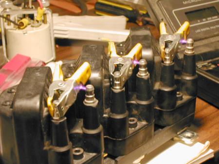
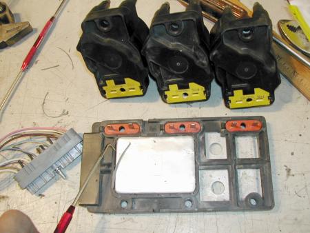
The following photo proves that the common wasted spark ignition is a series connected single coil. Note that the arc is going BETWEEN the two high voltage towers of each coil pack. If these two outputs were connected in parallel they would have the same voltage potential and no current would flow between them. But in fact, the secondary winding is isolated. The secondary winding is connected between the two high voltage terminals. The current travels out of one high voltage terminal to the first spark plug, then through the cylinder head to the second spark plug, then back to the other high voltage terminal on the ignition coil, thus completing the SERIES connected circuit.
Here is the web address and the article that the photos came from:
http://www.teglerizer.com/fi/megasquirt ... odule.html
----------------------------------------------------------

Here is the web address and the article that the diagram came from:
http://www.crypton.co.za/Tto%20know/Ign ... %20sp.html
----------------------------------------------------------
The following is an excerpt from: http://pages.zoom.co.uk/blitzracing/ignition.htm
"Wasted spark systems. This system uses one coil per 2 cylinders. This coil has one primary winding plus a secondary winding with an EHT lead at each end. The spark path starts at one end of the winding, travels down to the HT lead to one plug, through the cylinder head to the second plug, then jumps the gap in the opposite direction to the plug tip and back up the HT lead to the other end of the coil."
----------------------------------------------------------
Scott Novak
The following photo proves that the common wasted spark ignition is a series connected single coil. Note that the arc is going BETWEEN the two high voltage towers of each coil pack. If these two outputs were connected in parallel they would have the same voltage potential and no current would flow between them. But in fact, the secondary winding is isolated. The secondary winding is connected between the two high voltage terminals. The current travels out of one high voltage terminal to the first spark plug, then through the cylinder head to the second spark plug, then back to the other high voltage terminal on the ignition coil, thus completing the SERIES connected circuit.
Here is the web address and the article that the photos came from:
http://www.teglerizer.com/fi/megasquirt ... odule.html
----------------------------------------------------------
Here is the web address and the article that the diagram came from:
http://www.crypton.co.za/Tto%20know/Ign ... %20sp.html
----------------------------------------------------------
The following is an excerpt from: http://pages.zoom.co.uk/blitzracing/ignition.htm
"Wasted spark systems. This system uses one coil per 2 cylinders. This coil has one primary winding plus a secondary winding with an EHT lead at each end. The spark path starts at one end of the winding, travels down to the HT lead to one plug, through the cylinder head to the second plug, then jumps the gap in the opposite direction to the plug tip and back up the HT lead to the other end of the coil."
----------------------------------------------------------
Never replace and existing technology with and inferior one. And don't forget the KISS principle. There are times when it makes sense to use advanced technology, and other times when it doesn't. Elegant simplicity is what everyone should strive for. It's easy to make an over complicated system to perform a task. It is often very difficult to do the same job simply.iswinkels wrote:The whole world must just be turning to crap in your eyes then, because in case you didn’t notice… complex electronics are in everything.
Scott Novak
-
Scott Novak
- Posts: 522
- Joined: Mon Nov 08, 2004 1:31 pm
Everyone except for Ian will probably want to ignore this post.
----------------------------------------------------------
I've made an effort to explain what was incorrect about your explanations in a logical manner, but you refuse to even read my response. That is not what I'd call an intelligent discourse and I'm done trying to explain anything else to you.
Scott Novak
----------------------------------------------------------
Like hell you weren't. You DID take the first shot and I quote:iswinkels wrote:I was not taking a shot at your knowledge.
iswinkels wrote:No offence Scott, but I think you need to re-read your posts and make sure you get your details straight before posting. There are a lot of people on the forum that do long winded technical posts and that makes the forum great, but you've got to get the facts straight or you'll just end up confusing people that arent 100% in the know.
My statements are fairly precise. The precision often makes the statements rather long. If you had any kind of attention span you might be able to understand them.iswinkels wrote:If I were to take a shot I suggest you take the time to proof read your long winded posts so they read more clearly.
Excuse me? Spelling errors? If you re-read my posts you will see that they are few and far between. Your responses are riddled with spelling errors. As well as using errors, such as using "Your" instead of the correct "You're", that you used in your last sentence. If you are going to accuse me of mistakes, accuse me of mistakes that I have actually made. While you are at it, you might think about using a spell checker.iswinkels wrote:You could fix your grammatical and spelling errors while your at it.
If you can find any errors you are welcome to point them out with a logical and intelligent explanation. As far as I can see, my only error so far was a semantic one concerning wasted spark ignitions, and that's a matter of which definitions you choose to use.iswinkels wrote:But 'Im sure you know for a fact that you were incorrect in quite a few area’s with your explanations in your posts.
I've made an effort to explain what was incorrect about your explanations in a logical manner, but you refuse to even read my response. That is not what I'd call an intelligent discourse and I'm done trying to explain anything else to you.
Scott Novak
-
Frallan

- Posts: 667
- Joined: Sun Mar 30, 2003 12:01 am
Guys!
I really wish I could offer the two of you a ticket to a nice place were we could sit, meet and just chat around ACVW´s, internet and how fantastic it is, all this infomation sharing.
I would tell you all the stories on how I met so many new people in really odd places in the world with same interests like me and I am sure we would talk ignitions too.
I am also 99% sure that both of you guys would find this meeting really interesting and probably we would not shout at each other.
Agree on everything, no way but who does?
Would we take shots at each other for having strange dialects or using wrong grammatics, nope, I do not think so.
Just give a thought. Please.
What just happened here is so common and no one of us needs it.
We all love this information and deeper knowledge.
A moderator is probably just now contemplating to remove this thread from the forum and who wins and who loses then?