All the hoses are molded pre-shaped pieces surf. Took a lot of trial and error, but I was able to identify everything I needed in the end. For the hard lines, I found I was able to bend the thin wall aluminum with my Pro-tools bender up to 1" size. 1.25" it would kink every time, so for that it's all straight sections plus one area that I'm having to have a curved tube welded to a straight section. The pre-curved tubes I got from Columbia River:
http://www.mandrel-bends.com/catalog/
I beaded all the tubes with the Earls beading tools.
Jeff
Deserter GS to Suby EJ20 Turbo
-
dlamyle

- Posts: 153
- Joined: Tue Jul 09, 2013 11:27 am
Re: Deserter GS to Suby EJ20 Turbo
I usually take a piece of welding rod or wire hanger bent to the shape I need and a short piece of tube of the right diameter and ask the guy if I can search through their rack for a close match. Never been told no.surfbeetle wrote:I'm dreading going into Pep Boys or wherever and asking for hose.
1968 Karmann Ghia, JDM EJ205, Subarugears, OBX LSD, Blouch 16g XTR, Killer B Headers, DW 750cc, Meth Inj, Cobb AP w/Mach V 22psi Dyno tune (332whp)
Videos
Build Thread
Videos
Build Thread
-
GS guy

- Posts: 909
- Joined: Wed Nov 06, 2002 12:01 am
Re: Deserter GS to Suby EJ20 Turbo
I've got a bunch of hose PNs with descriptions/pics for the hoses I've used - be glad to share them with anyone looking for something specific. The only hitch with looking at your local FLAPS is you only see what they have in stock, which is likely just the best sellers. There are thousands of specially molded hoses of various shapes and sizes. I've had good luck just googling "molded hose (and size)" and looking at the pics. If one looks promising I'll move on to the website that hosted the pic and try to dig up further info.
Rock Auto is an excellent site to check on basic hose info - if you have the PN. Great place to buy from too, best shipping prices I've found.
Jeff
Rock Auto is an excellent site to check on basic hose info - if you have the PN. Great place to buy from too, best shipping prices I've found.
Jeff
-
GS guy
- Posts: 909
- Joined: Wed Nov 06, 2002 12:01 am
Re: Deserter GS to Suby EJ20 Turbo
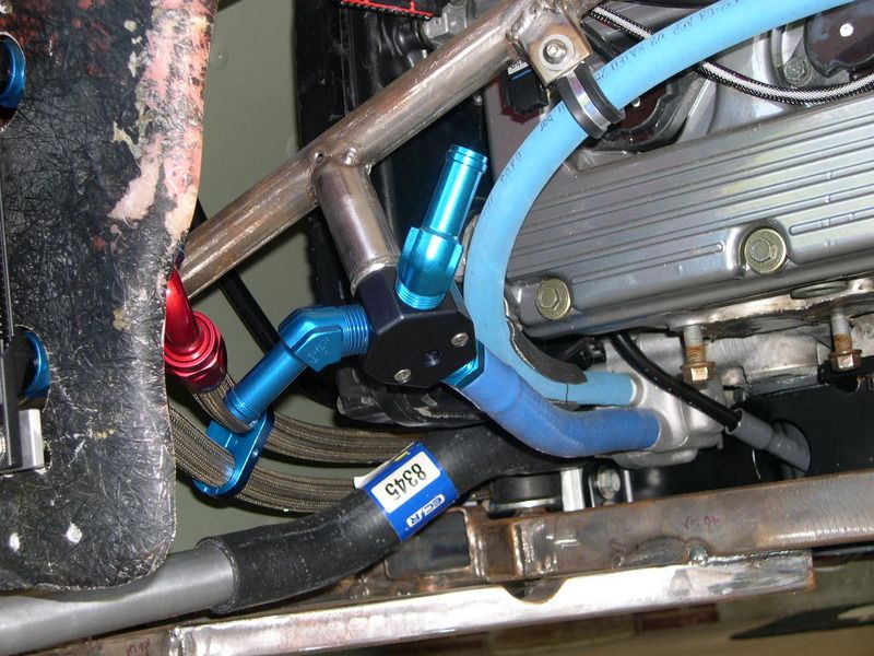
Another year gone by..... and not as productive on the GS project as I would have liked. Guess I'm firmly into the long term build category! More progress though - managed to get all my aluminum plumbing lines welded up with bleeder fittings and taps for the cockpit heater. At least they're ready to bolt-on and go. Got the Y junction mount tacked to the frame (engine will have to come back out for access to fully weld. Forward facing (left-side) fitting comes from the heater, rear (right-side) comes from the upper coolant manifold heater outlet port. The lighter blue line is coming from the coolant fill/reservoir.
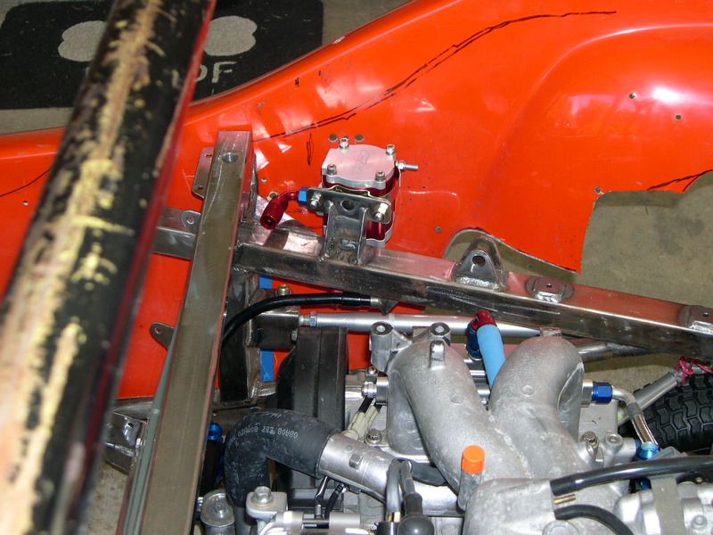
A few more brackets on the frame attached, and critically the rear fuel filter mount. In fact, I had to re-install the engine and some of the rear suspension just to install this part! Trickiest is the fuel inlet to the filter at the bottom of the filter. It has to snake between a suspension trailing link and clear rear e-brake cable guides. Placement on the chassis allowed for very little fudge room.
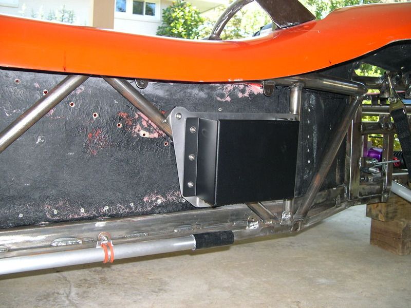
Battery box mounts tacked in place.
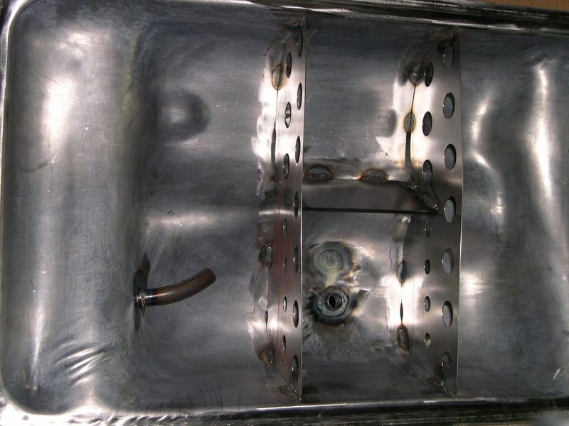
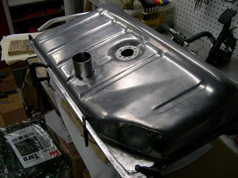
This fall I've been working on a suitable fuel tank. Originally thinking I would have to build a full custom fuel cell ($$$) because of the new chassis members up front, but one afternoon messing around with an old tank I realized that by flipping the tank front to rear it fit perfectly with chassis and steering underneath. For whatever reason, the Beetle tank has more underside clearance on the passenger side than drivers and also a "rear sump" layout that fouled my R&P steering links and front firewall cross brace on the frame. Turning it around solved both of these issues! However, now the top design was out of whack with a steeply angled top rear to front. Based on this knowledge, I ordered up a new tank to modify and first thing - cut it into two. With top rotated 180 deg. to bottom, fitment was like it was made to be that way even with all the custom chassis work and suspension up front. And while I'm in there.... proceeded to add custom 3/8NPT fuel inlet/outlet and vent bungs and internal baffling to help control fuel slosh and feed the external EFI pump without running "dry". Still need to precision locate the fuel filler neck as the original now closed off - going for a center fill towards rear of the tank (centered with hood).
Close-up with line of sight from steering rack, past lower tank up to round opening in bodywork and lower steering column support for connecting shaft - should clear great!
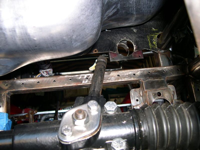
Unfortunately now winter is starting to set in and outside build season time has run out for the year.
I still need to do some tweaking to my body mounts at the front of the chassis - don't like how they came out with current body fitment, and that needs to be completed before I can accurately locate the hood to drill the tank top for the filler neck (domino affect). That'll probably have to wait until spring 2016. Plan is to have fuel filler exposed while hood is closed, yet it will be attached to the tank.
Jeff
A few more brackets on the frame attached, and critically the rear fuel filter mount. In fact, I had to re-install the engine and some of the rear suspension just to install this part! Trickiest is the fuel inlet to the filter at the bottom of the filter. It has to snake between a suspension trailing link and clear rear e-brake cable guides. Placement on the chassis allowed for very little fudge room.
Battery box mounts tacked in place.
This fall I've been working on a suitable fuel tank. Originally thinking I would have to build a full custom fuel cell ($$$) because of the new chassis members up front, but one afternoon messing around with an old tank I realized that by flipping the tank front to rear it fit perfectly with chassis and steering underneath. For whatever reason, the Beetle tank has more underside clearance on the passenger side than drivers and also a "rear sump" layout that fouled my R&P steering links and front firewall cross brace on the frame. Turning it around solved both of these issues! However, now the top design was out of whack with a steeply angled top rear to front. Based on this knowledge, I ordered up a new tank to modify and first thing - cut it into two. With top rotated 180 deg. to bottom, fitment was like it was made to be that way even with all the custom chassis work and suspension up front. And while I'm in there.... proceeded to add custom 3/8NPT fuel inlet/outlet and vent bungs and internal baffling to help control fuel slosh and feed the external EFI pump without running "dry". Still need to precision locate the fuel filler neck as the original now closed off - going for a center fill towards rear of the tank (centered with hood).
Close-up with line of sight from steering rack, past lower tank up to round opening in bodywork and lower steering column support for connecting shaft - should clear great!
Unfortunately now winter is starting to set in and outside build season time has run out for the year.
I still need to do some tweaking to my body mounts at the front of the chassis - don't like how they came out with current body fitment, and that needs to be completed before I can accurately locate the hood to drill the tank top for the filler neck (domino affect). That'll probably have to wait until spring 2016. Plan is to have fuel filler exposed while hood is closed, yet it will be attached to the tank.
Jeff
-
GS guy
- Posts: 909
- Joined: Wed Nov 06, 2002 12:01 am
Re: Deserter GS to Suby EJ20 Turbo
Man, time sure flies! I guess this will be an "annual" update. 
This one will focus on the A-A intercooler - and specifically how I'm hoping to get airflow through it. With the mid-engine layout, I can't rely on ram-air at the front of the car for IC airflow. One option is to use air-water intercooling, but that requires a a completely separate cooling "system": hoses, pump, controls, reservoir, radiator, etc. From the beginning I wanted to take the simplest route - and all the hardware and complexity of an A-W system didn't fit well into that line of thinking. I'd hoped to utilize a passive system of natural high-pressure air to feed and cool the A-A IC, but as the hardware came together it became apparent there just wasn't enough available space to duct a sufficient amount of air from potential sources (namely the side pods or under the car). Being an open cockpit, I know the cockpit itself will present a low-pressure zone, which I believe will likely extend back over the engine cover to some extent. Having ridden in 3 different GS cars, it is clearly apparent that higher pressure air forms under the car and flows back up into the engine compartment - then tries to enter the cockpit, typically by the forward facing "scoop", or any other opening between cockpit and engine bay.
A good look of the engine cover scoop is shown in this pic of the "Dearborn" classic Green GS:
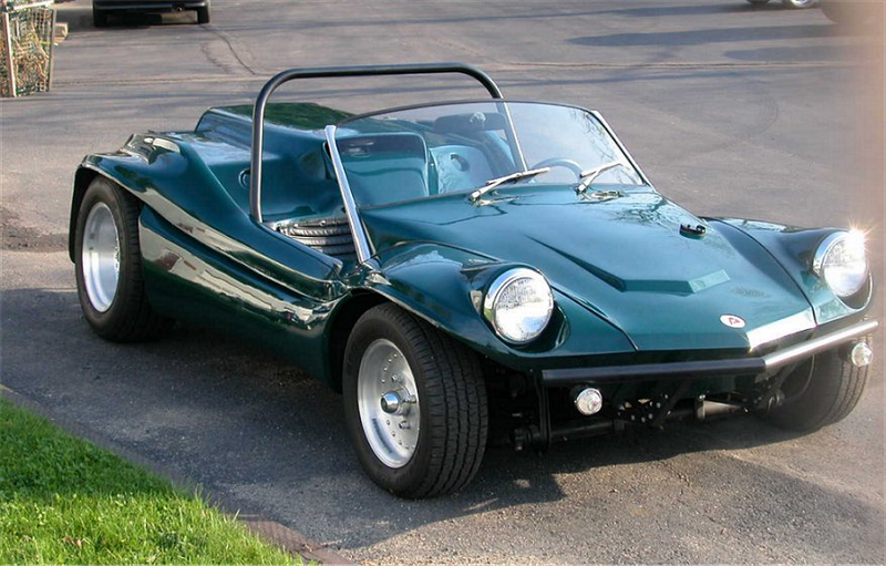
The "scoop" is open at the front and rear to the outside air and engine compartment below. Due the higher pressure zone in the engine bay, the forward "scoop" typically acts as an outlet for this warm (or hot) air - right into the cockpit behind your head! Because of that, most simply block it off making it more cosmetic instead of a functioning air-flow device. Some even utilized it for a cockpit heat source in the winter! No idea what is happening at the rear "outlet" end of the scoop - although having seen airflow studies of other cars and buggies, I suspect there may actually be some airflow curling up from under the car and maybe from above, curling back forwards and into the scoop! This would likely be (mostly?) pre-heated air from the engine, so probably not too useful as a source of cool air? Once I can get the car in a drivable state I'll do some manometer testing and find out for sure what's happening back there.
Back to the intercooler - I positioned the IC just under the scoop, towards the rear of the car.

This position was mostly dictated by placement of exhaust (pre and post turbo), throttle body intake position and turbo placement. Limited room played a large roll in determining the position. It sits underneath and slightly up "into" the scoop with a couple inches of overhead clearance.
Seems natural to just "cut a hole" in the scoop above the IC, seal it to the hole and let the high pressure air underneath blow up and out the top? I believe that would be the "natural" air-flow pattern. All that HOT engine air - no go. No room underneath either to fit a fan to pull air from the top down - intake ducting and chassis members taking up that space. But all that fresh air sitting just above the IC, above the scoop and just needing a way to get it down and through the IC. 80's era F1 scoop sitting high above the cockpit??? eh, no.
So the best idea I could come up with is a blow-through fan, and a way to seal the top of the IC to the bottom of the engine cover/scoop, using the scoop to form a sealed plenum above the IC. Plan is to seal IC to this plenum (when the cover is down), then provide an opening towards the top/rear for fresh air inlet, back away from the cockpit to hopefully keep the fan noise down when it cranks up to full speed.
First a flange is needed surrounding the IC.
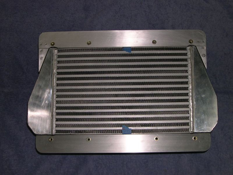
Spacers sit between fan mounting plate and IC flanges, working with a perimeter seal to form a very short fan shroud. Needs to be short fighting against limited overhead space.
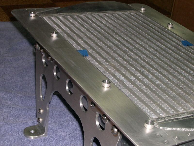
And with fan installed:
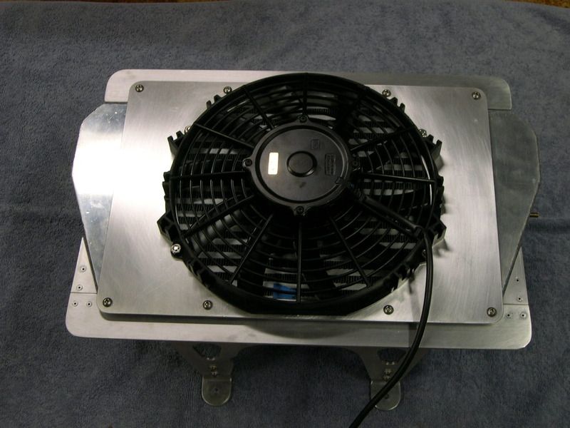
Still, the fan motor sits a little above the height of the scoop, so I'll have to fit some kind of "bump" there to clear. For inlet, pending airflow tests, I'll likely cut some narrow slit opening in the scoop top near the rear with hex-grill material fitted to the openings.
Much more to come, though I'm not so sure this is ending up being less "complex" than the A-W setup!
Jeff
This one will focus on the A-A intercooler - and specifically how I'm hoping to get airflow through it. With the mid-engine layout, I can't rely on ram-air at the front of the car for IC airflow. One option is to use air-water intercooling, but that requires a a completely separate cooling "system": hoses, pump, controls, reservoir, radiator, etc. From the beginning I wanted to take the simplest route - and all the hardware and complexity of an A-W system didn't fit well into that line of thinking. I'd hoped to utilize a passive system of natural high-pressure air to feed and cool the A-A IC, but as the hardware came together it became apparent there just wasn't enough available space to duct a sufficient amount of air from potential sources (namely the side pods or under the car). Being an open cockpit, I know the cockpit itself will present a low-pressure zone, which I believe will likely extend back over the engine cover to some extent. Having ridden in 3 different GS cars, it is clearly apparent that higher pressure air forms under the car and flows back up into the engine compartment - then tries to enter the cockpit, typically by the forward facing "scoop", or any other opening between cockpit and engine bay.
A good look of the engine cover scoop is shown in this pic of the "Dearborn" classic Green GS:
The "scoop" is open at the front and rear to the outside air and engine compartment below. Due the higher pressure zone in the engine bay, the forward "scoop" typically acts as an outlet for this warm (or hot) air - right into the cockpit behind your head! Because of that, most simply block it off making it more cosmetic instead of a functioning air-flow device. Some even utilized it for a cockpit heat source in the winter! No idea what is happening at the rear "outlet" end of the scoop - although having seen airflow studies of other cars and buggies, I suspect there may actually be some airflow curling up from under the car and maybe from above, curling back forwards and into the scoop! This would likely be (mostly?) pre-heated air from the engine, so probably not too useful as a source of cool air? Once I can get the car in a drivable state I'll do some manometer testing and find out for sure what's happening back there.
Back to the intercooler - I positioned the IC just under the scoop, towards the rear of the car.
This position was mostly dictated by placement of exhaust (pre and post turbo), throttle body intake position and turbo placement. Limited room played a large roll in determining the position. It sits underneath and slightly up "into" the scoop with a couple inches of overhead clearance.
Seems natural to just "cut a hole" in the scoop above the IC, seal it to the hole and let the high pressure air underneath blow up and out the top? I believe that would be the "natural" air-flow pattern. All that HOT engine air - no go. No room underneath either to fit a fan to pull air from the top down - intake ducting and chassis members taking up that space. But all that fresh air sitting just above the IC, above the scoop and just needing a way to get it down and through the IC. 80's era F1 scoop sitting high above the cockpit??? eh, no.
So the best idea I could come up with is a blow-through fan, and a way to seal the top of the IC to the bottom of the engine cover/scoop, using the scoop to form a sealed plenum above the IC. Plan is to seal IC to this plenum (when the cover is down), then provide an opening towards the top/rear for fresh air inlet, back away from the cockpit to hopefully keep the fan noise down when it cranks up to full speed.
First a flange is needed surrounding the IC.
Spacers sit between fan mounting plate and IC flanges, working with a perimeter seal to form a very short fan shroud. Needs to be short fighting against limited overhead space.
And with fan installed:
Still, the fan motor sits a little above the height of the scoop, so I'll have to fit some kind of "bump" there to clear. For inlet, pending airflow tests, I'll likely cut some narrow slit opening in the scoop top near the rear with hex-grill material fitted to the openings.
Much more to come, though I'm not so sure this is ending up being less "complex" than the A-W setup!
Jeff
-
GS guy
- Posts: 909
- Joined: Wed Nov 06, 2002 12:01 am
Re: Deserter GS to Suby EJ20 Turbo
Onto controlling the fan. Seems like you need two modes of fan operation, at least in my case.
1) Whenever the IC sees temps starting to rise above ambient - like idling in traffic, engine compartment heat soak, etc. How much above??? Best guess TBD. So adjustability of a thermostatic switch would be nice. How much fan? Ideally I think a pulse-width-modulated fan speed tied to temperature would be ideal - increasing fan speed as the temperature rises. I couldn't find any kind of control system that would perform that function in the temperature ranges the intake system works in, say around 100F up to 150F? So I at least want a fixed "low speed" setting to get the air flowing.
2) Boost onset. I want the fan to come on full speed whenever the boost exceeds some threshold - guessing around 5-7lbs of boost would be a good starting point. This should starting the cooling process "before" the IC is allowed to start heating up too much.
So for #2, I'm going to use the Megasquirt to control that function. An output will use a MAP reading to switch the fan on/off - full speed.
For #1 - I'm mostly out of "easy" outputs on my MS2, plus I really wanted to base this on the temperature of the IC itself, not IAT. Search began for a compact thermostatic switch, and I wound up attempting this with a "snap" switch. These are typically used with air heating systems, wood stoves with blower fans and the like. Inexpensive, and the slick thing is they are available at a fixed temperature and adjustable and in the correct ranges! I mounted the switch so that the "sensing" surface is pressed against the outside of the IC housing, plus I'll use some thermal paste to assist in heat transfer. For speed control, I picked up a high amperage (40A) PWM electric motor/fan controller (also adjustable) and I'll just wire these through a relay activated when the ignition switch is in the key-on position.
Here's the snap switch mounted to the IC:
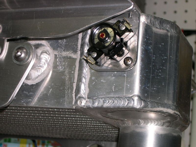
Seems like a good idea on paper? Actual functionality TBD once everything is running!
Jeff
1) Whenever the IC sees temps starting to rise above ambient - like idling in traffic, engine compartment heat soak, etc. How much above??? Best guess TBD. So adjustability of a thermostatic switch would be nice. How much fan? Ideally I think a pulse-width-modulated fan speed tied to temperature would be ideal - increasing fan speed as the temperature rises. I couldn't find any kind of control system that would perform that function in the temperature ranges the intake system works in, say around 100F up to 150F? So I at least want a fixed "low speed" setting to get the air flowing.
2) Boost onset. I want the fan to come on full speed whenever the boost exceeds some threshold - guessing around 5-7lbs of boost would be a good starting point. This should starting the cooling process "before" the IC is allowed to start heating up too much.
So for #2, I'm going to use the Megasquirt to control that function. An output will use a MAP reading to switch the fan on/off - full speed.
For #1 - I'm mostly out of "easy" outputs on my MS2, plus I really wanted to base this on the temperature of the IC itself, not IAT. Search began for a compact thermostatic switch, and I wound up attempting this with a "snap" switch. These are typically used with air heating systems, wood stoves with blower fans and the like. Inexpensive, and the slick thing is they are available at a fixed temperature and adjustable and in the correct ranges! I mounted the switch so that the "sensing" surface is pressed against the outside of the IC housing, plus I'll use some thermal paste to assist in heat transfer. For speed control, I picked up a high amperage (40A) PWM electric motor/fan controller (also adjustable) and I'll just wire these through a relay activated when the ignition switch is in the key-on position.
Here's the snap switch mounted to the IC:
Seems like a good idea on paper? Actual functionality TBD once everything is running!
Jeff
-
panel

- Posts: 4201
- Joined: Sun Sep 24, 2000 12:01 am
Re: Deserter GS to Suby EJ20 Turbo
Jeff , care to share where you got the 'snap' switch from ?
'65 Bus with a JDM Subaru EJ20 Turbo
Built by Germans powered by Japanese and brought together by Canadians
Built by Germans powered by Japanese and brought together by Canadians
-
GS guy
- Posts: 909
- Joined: Wed Nov 06, 2002 12:01 am
Re: Deserter GS to Suby EJ20 Turbo
Sure panel,panel wrote:Jeff , care to share where you got the 'snap' switch from ?
I'd never heard of a "snap" switch before starting a search for some kind of thermostatic switch. Lots of info about these on Google searches and youtube - how they work, etc.
-
GS guy
- Posts: 909
- Joined: Wed Nov 06, 2002 12:01 am
Re: Deserter GS to Suby EJ20 Turbo
FWIW - here is the motor speed controller I selected:
Jeff
Jeff
-
GS guy
- Posts: 909
- Joined: Wed Nov 06, 2002 12:01 am
Re: Deserter GS to Suby EJ20 Turbo
A 1-day warm spell provided the opportunity to make some more progress on the fuel tank. As noted in the posts above, the tank had been split with internal baffling and ports added. Last thing to do before welding the two halves back together was the filler neck. Also as previously noted, I wasn't 100% happy with the general body fit at the forward mounting points - these are just forward of the tank right at the nose. They were just a little too high, which caused the body to "tweaked" a little at the front, resulting in a hood fit that just wasn't quite right.
Here are the 3 offending mounts. I'd already relieved the bodywork to try and lower it around the mounts, but it wasn't enough:
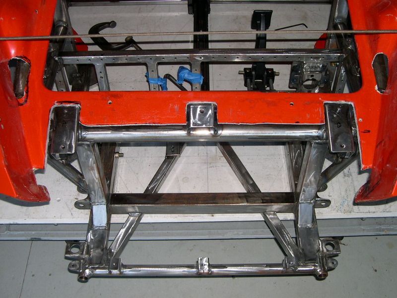
Soooo, during last year I bit the bullet and out came the cut-off wheel and some slicing and dicing, trimming metal back, re-fitting and tacking with (body back on), and once satisfied full welding. This was a royal PITA (for 1/4"!), but the only way to really "fix" the problem. Just 1/4" too much.
Now that the body was sitting properly, I could re-focus on the filler neck. I'd located on the hood a front-rear center line, and approximately where I wanted the neck towards the rear (and highest point) on the tank. A 1/4" hole in the hood located the spot, and using a 1/4" transfer punch and an alignment block (keeping the punch square with the hood), located the drill spot on the tank below. I also needed to verify the angle of the punch to tank so I could re-produce this with the new neck (keeping the neck square with the hood) - worked out to 9.5 degrees off normal. Hood back off, drilled a 1/4" hole in the tank, hood back on, re-check the hole alignment hood to tank, then finally time for the "big" hole. I'd previously tacked the tank halves together temporarily to keep the halves from shifting, then c-clamped the tank to body. This turned out to be a great way to support the tank for hole drilling. My filler neck is a piece of 2.25" exhaust tube, so need a tightly fitted hole to mount the tube in the tank. First scribing the 2.25" finish hole size in the hood, I then used a 2-1/8" hole saw to create a slightly undersize hole that I could then carefully open up to the finished size using a carbide burr and then coarse sanding drum in the drill motor. Lots of test-fitting the tube section into the hole, grinding, fitting, repeat. This worked great to eventually get a "tight" fit of tube to tank, all the while working the 9.5 degree tube to tank angle.
After that, the tube was tacked to the tank to hold the position, then I re-split the tank halves to clean up internally from all the drilling and grinding debris. Final wipe-down inside with some denatured alcohol/lint-free wipes, and a very 'light" application of Gibbs on the baffles to keep from rusting until I can internally coat the tank, and she's clamped back together for final welding. I'll leave that part to my welding guy as I don't trust myself to get nice, non-porous welds in the thin metal of the tank.
That was a lot of tedious "fitting and fiddling" but necessary to match the filler cap to hood angle. I want to make a hinged/opening hood, and the cap needs to be tightly fitted to the hood opening to align properly as cap will be exposed when hood is closed. I won't open up the hood "hole" for the cap until final body fitting, just before painting.
Jeff
Here are the 3 offending mounts. I'd already relieved the bodywork to try and lower it around the mounts, but it wasn't enough:
Soooo, during last year I bit the bullet and out came the cut-off wheel and some slicing and dicing, trimming metal back, re-fitting and tacking with (body back on), and once satisfied full welding. This was a royal PITA (for 1/4"!), but the only way to really "fix" the problem. Just 1/4" too much.
Now that the body was sitting properly, I could re-focus on the filler neck. I'd located on the hood a front-rear center line, and approximately where I wanted the neck towards the rear (and highest point) on the tank. A 1/4" hole in the hood located the spot, and using a 1/4" transfer punch and an alignment block (keeping the punch square with the hood), located the drill spot on the tank below. I also needed to verify the angle of the punch to tank so I could re-produce this with the new neck (keeping the neck square with the hood) - worked out to 9.5 degrees off normal. Hood back off, drilled a 1/4" hole in the tank, hood back on, re-check the hole alignment hood to tank, then finally time for the "big" hole. I'd previously tacked the tank halves together temporarily to keep the halves from shifting, then c-clamped the tank to body. This turned out to be a great way to support the tank for hole drilling. My filler neck is a piece of 2.25" exhaust tube, so need a tightly fitted hole to mount the tube in the tank. First scribing the 2.25" finish hole size in the hood, I then used a 2-1/8" hole saw to create a slightly undersize hole that I could then carefully open up to the finished size using a carbide burr and then coarse sanding drum in the drill motor. Lots of test-fitting the tube section into the hole, grinding, fitting, repeat. This worked great to eventually get a "tight" fit of tube to tank, all the while working the 9.5 degree tube to tank angle.
After that, the tube was tacked to the tank to hold the position, then I re-split the tank halves to clean up internally from all the drilling and grinding debris. Final wipe-down inside with some denatured alcohol/lint-free wipes, and a very 'light" application of Gibbs on the baffles to keep from rusting until I can internally coat the tank, and she's clamped back together for final welding. I'll leave that part to my welding guy as I don't trust myself to get nice, non-porous welds in the thin metal of the tank.
That was a lot of tedious "fitting and fiddling" but necessary to match the filler cap to hood angle. I want to make a hinged/opening hood, and the cap needs to be tightly fitted to the hood opening to align properly as cap will be exposed when hood is closed. I won't open up the hood "hole" for the cap until final body fitting, just before painting.
Jeff
-
Vancouver98STi

- Posts: 3
- Joined: Thu Mar 02, 2017 6:26 pm
Re: Deserter GS to Suby EJ20 Turbo
Jeff, forgive me for quoting a post of yours from almost five years ago... but I was very glad to find what you had posted, and I was hoping to ask you a few questions.
I've very recently acquired a '98 JDM Subaru Impreza STi wagon with this same engine, the EJ20K. It's my first Subaru, my first turbo... heck it's my first wagon!
Your posts on this topic, along with their diagrams, made good sense to me. Your custom setup is rather clever, and I understand (at least I believe I do) how it works. However, I'm still a little puzzled by a couple of things...
What was the reason that you did away with one of the original PCV air inlets connecting to the intake? Was it simply to do away with the need for another catch can plumbed into the second air inlet? Do you anticipate any detrimental effect at all from combining the two inlets? Would you still have gone this route if you had retained the OEM intake?
And speaking of another catch can, I was very surprised to see that you didn't add one between the crankcase and the PCV valve/intake manifold.
So please don't take my questions as any form of critism of how you've decided to tackle this. Your whole project is beautifully done. I'd just like to learn a bit more on what your thoughts are on this PCV system. Thanks.
-Patrick
-
GS guy
- Posts: 909
- Joined: Wed Nov 06, 2002 12:01 am
Re: Deserter GS to Suby EJ20 Turbo
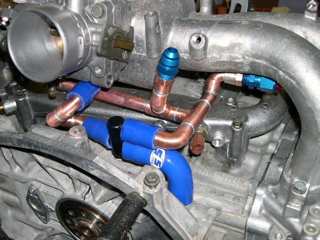
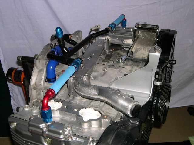
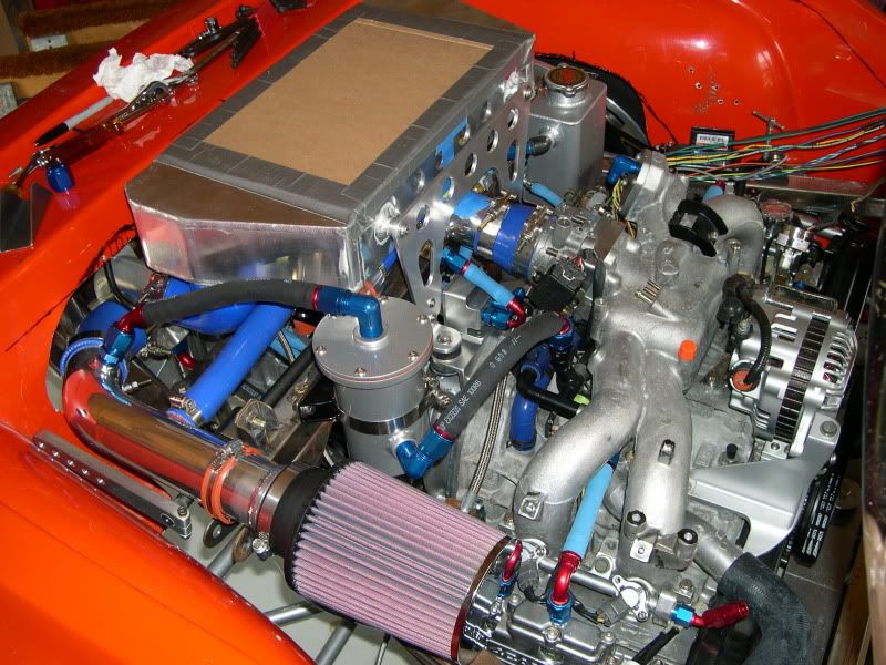
Partick - glad you were able to make some sense from all my rambling! Also funny you brought up the PCV system as I had recently been implementing some mods to the parts. No changes to the layout/flow, but I wanted a little more "flexibility" in the hoses that went to the valve covers. The Aeroquip push-lock hose is really stiff, similar to regular SS hose. I wasn't 100% happy I'd gotten the length of the set-up exactly right from valve cover to valve cover, as I'd noticed some seepage from the fittings at the valve covers (just from the oil on the AN fitting threads - engine has not yet been run). I decided to replace the Aeroquip hose with standard oil/trans cooler hose and modify the fittings for easier slip-on hose connection. Not much pressure here, and this will give some more flexibility when fitting the system onto the engine. Once you assemble the Aeroquip fittings to the push-lock hose, the only way to "adjust" is is to cut the hose off and start over!
I made this system as physical appearance of the OEM layout wasn't very aesthetically appealing, and all the molded hoses were hard as rock. Much more difficult finding molded oil rated hoses, unlike coolant hoses. So I started from scratch.
Back to your questions. I think a PCV system is essential to any NA engine as a self-cleaning device - it purges all the water vapor and combustion by-products from the crankcase automatically. I once tried to eliminate the PCV system from a "hot-rodded" Toyota and just run a crankcase vent/filter (like a VW engine) - and shortly after started getting oozy sludge build-up. Switched that one back and no more problems!
I think when you supercharge an engine, that's when venting the crankcase gets tricky. While you're NA, no problem with the PCV system, it works great ALA the engine is tight with nominal blow-by (and my thoughts of Not needing a catch can for that scenario). Now this is for a street engine I'm talking about. Highly tuned race engines may be built with looser tolerances for higher RPMs, higher heat and that would be a different ball game for crankcase venting.
My thinking about boosted situations is the PCV valve closes when manifold pressure goes above crankcase pressure. Any additional blow-by in the crankcase has to go somewhere, and I believe it has to vent from the main crankcase vent (at the back of the motor on mine) and a little at the valve covers. The low pressure zone it wants to go towards is in the intake duct - up-stream of the turbo (since the turbo is sucking in lots of air!). Whatever comes from the crankcase makes its way through the turbo, IC and into the intake. That's where I wanted to "catch" any oil in those boosted-situation blow-by gasses.
The restrictor in the PCV plumbing is important (not shown very clearly in the OEM diagram) to bias the crankcase pressure to go in the wanted direction.
Hope this makes sense? Seems to make sense to me thinking through it?
Jeff
-
Vancouver98STi
- Posts: 3
- Joined: Thu Mar 02, 2017 6:26 pm
Re: Deserter GS to Suby EJ20 Turbo
Jeff, thanks for your response!

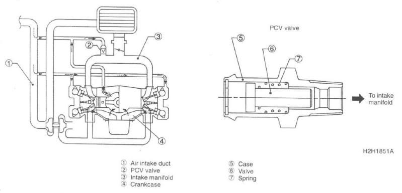
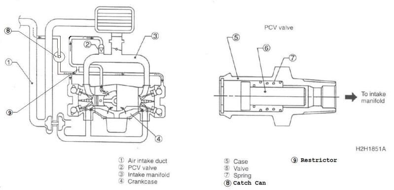
In the diagrams below, I took a guess as to where the restrictor is located. I thought these diagrams might be helpful posting here for anyone reading this thread who might also have an interest in the PCV systems of these engines.
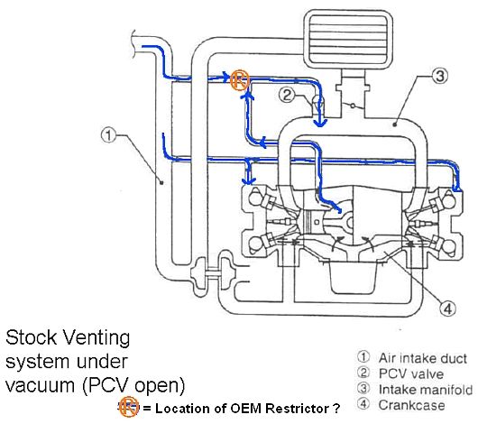
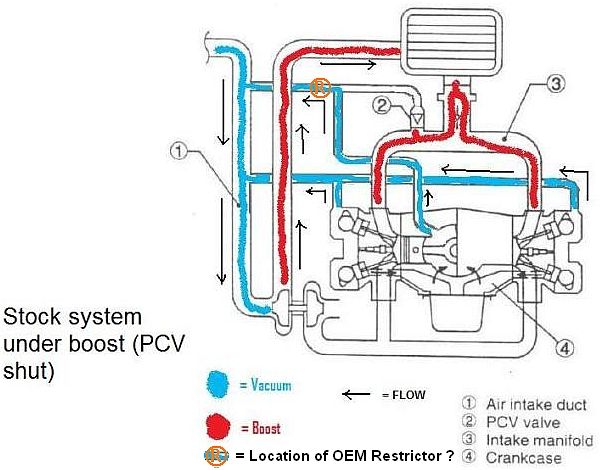
As you referred to earlier, it's rather interesting how the flow of air through much of the PCV system actually reverses while the engine is under boost. Because of that, any catch can installed at the junction of the PCV air inlet(s) and the (pre-turbo) intake needs to be oriented in the correct (inlet/outlet) direction! With that in mind, are you concerned at all that the lower tube on your catch can (which becomes the outlet during NA operation) might be too close to the bottom of the can and will allow collected oil to be sucked out and into the (unprotected) PCV valve/intake manifold? Perhaps a catch can for the PCV valve/intake manifold might still be a good idea!
Okay, I see what you're saying. However, for those with perhaps less of a "tight" engine (due to normal wear and tear), I guess that's why many people install a catch can between the crankcase and the PCV valve/intake manifold. A lot of crankcase air (and potential oil vapours) are being sucked through there. The EJ20K engine in my Impreza STi seems to run quite well, but it's got 140,000 km on it, so I'm sure it's a little looser than it was back in '98.
I agree with all that completely... but you didn't address my questions (copied below).GS guy wrote: ↑Sat Mar 04, 2017 5:34 am My thinking about boosted situations is the PCV valve closes when manifold pressure goes above crankcase pressure. Any additional blow-by in the crankcase has to go somewhere, and I believe it has to vent from the main crankcase vent (at the back of the motor on mine) and a little at the valve covers. The low pressure zone it wants to go towards is in the intake duct - up-stream of the turbo (since the turbo is sucking in lots of air!). Whatever comes from the crankcase makes its way through the turbo, IC and into the intake. That's where I wanted to "catch" any oil in those boosted-situation blow-by gasses.
The diagrams I've uploaded below show the two inlets I'm referring to.Vancouver98STi wrote: ↑Thu Mar 02, 2017 11:54 pm Patrick: What was the reason that you did away with one of the original PCV air inlets connecting to the intake? Was it simply to do away with the need for another catch can plumbed into the second air inlet? Do you anticipate any detrimental effect at all from combining the two inlets? Would you still have gone this route if you had retained the OEM intake?
I haven't taken my PCV system apart yet, so I don't know where the restrictor is located or the size of the opening. Do you recall offhand the size of the hole?
In the diagrams below, I took a guess as to where the restrictor is located. I thought these diagrams might be helpful posting here for anyone reading this thread who might also have an interest in the PCV systems of these engines.
As you referred to earlier, it's rather interesting how the flow of air through much of the PCV system actually reverses while the engine is under boost. Because of that, any catch can installed at the junction of the PCV air inlet(s) and the (pre-turbo) intake needs to be oriented in the correct (inlet/outlet) direction! With that in mind, are you concerned at all that the lower tube on your catch can (which becomes the outlet during NA operation) might be too close to the bottom of the can and will allow collected oil to be sucked out and into the (unprotected) PCV valve/intake manifold? Perhaps a catch can for the PCV valve/intake manifold might still be a good idea!
Last edited by Vancouver98STi on Sat Mar 04, 2017 1:30 pm, edited 1 time in total.
-Patrick
-
Piledriver

- Moderator
- Posts: 22520
- Joined: Sat Feb 16, 2002 12:01 am
Re: Deserter GS to Suby EJ20 Turbo
Closely examining a VW 1.8T PCV diagram is suggested.
It uses a few check valves to steer PCV under various conditions, and uses a vacuum generator that literally leaks boost for airflow for PCV and brake booster vacuum.
The steering valves most folks retrofit are from US Plastics for about a buck each.
These are nice fast disc check valves with viton diaphragms, I just wish they made bigger..
Addendum to Newtons first law:
zero vehicles on jackstands, square gets a fresh 090 and 1911, cabby gets a blower.
EZ3.6 Vanagon after that.(mounted, needs everything finished) then Creamsicle.
zero vehicles on jackstands, square gets a fresh 090 and 1911, cabby gets a blower.
EZ3.6 Vanagon after that.(mounted, needs everything finished) then Creamsicle.
-
GS guy
- Posts: 909
- Joined: Wed Nov 06, 2002 12:01 am
Re: Deserter GS to Suby EJ20 Turbo
Yea - I'm not sure the reasoning behind the 2 inlet paths in the original PCV piping? The actual inlets are only about 8" apart on my tube and other than separate feed paths for the PCV valve and valve covers, I can't see a reason it was set up this way? You're talking 5/8" diameter tubes and I cant imagine there is enough flow going through the system to tax that flow capability (even with my one inlet path).
I guess in the end - you have to decide if you want to modify the system (as I did), and whether you'll keep both separated flow paths as OEM. I think if you did keep both paths, you'd probably want to incorporate separate catch cans for each?
There's some discussion on the Factory Five 818 board about Subaru catch cans, maybe offering some more insight (or other options). I just don't have the physical "room" to fit another catch can. I'll definitely keep an eye on it, but I don't think it'll fill up enough to cause any "ingestion" issues during boost. It would probably need about a 1/2pt or more of oil in it to start causing problems with teh overall size of the can.
The restrictor is positioned exactly as you have it depicted in the sketches, and flow paths as I believe they take during both operating modes. Nice depictions! The restrictor size is a #1 drill, 0.228" exactly (nice snug fit in the OEM T fitting hole).
I think anytime you modify something from stock, you have to make your "best guestimate" whether the modified set-up helps, has no effect, or hurts the operation. If it doesn't work - figure out a plan "B"!
Jeff