Yes, I am aware of that and it is probably what I am getting. The shop I go through said that is pretty much what is being produced now days. Up graded ones cost quite a bit more an my fenders limit travel.
Thanks for the concern
Lee
Update
On my way to Bend OR so quick reply for most of the day as we make stops for various reasons.
Based on what i am now hearing the CV thing apparently is changing a lot. Bus CVs, as I understand it, can be had with different size balls for different angles. For Thing CVs my source is getting bus CVs, the same thing for Type 4s as I was told. Not sure if this is true everywhere but if not I wouldn't be surprised it is coming. To go to anything with much bigger angles than the bus, the cost is in proportion to the degree of angle or... more is more!
As I said, before I pack the CVs and install them I am going to run the suspension through its full motion with out the torsion bars in place. Bodies like mine with full rear fenders you have a lot of other things to take into consideration than a Manx style buggy might have. I have the body mount holes drilled now so now I have to finish the fiber glassing to thicken up the fiber glass material and, if needed do some moving of the body a bit for rear wheel clearance.
Lee
Ol'fogasaurus black buggy
-
Ol'fogasaurus
- Posts: 17881
- Joined: Mon Nov 13, 2006 10:17 pm
Re: Ol'fogasaurus black buggy
I just got my parts in to do the brake and CV change over. I know some of you guys aren't cool with EMPI parts but since I don't shop on line anymore (I was compromised by some jerk or jerkette) I bought from a my reliable source here in town: Autovice in Lynnwood WA. Doug had been good to me on stuff and information so it was him I dealt with.
I'm in the process of opening things up and taking pictures so more later on.
Lee
I'm in the process of opening things up and taking pictures so more later on.
Lee
-
Ol'fogasaurus
- Posts: 17881
- Joined: Mon Nov 13, 2006 10:17 pm
Re: Ol'fogasaurus black buggy

This is the pile of stuff that came in for me; I still have a few more things that will be in later today.

This is the kit for a Kaffer/truss bar which they call a "Shock Tower Brace" (if you are trying to find one). For those who don't know it is to add some support to the transaxle/engine mount to keep it from failing on off-road or competition excursions'. Not a bad I idea to have anyway as the metal of these old cars has to be degrading some.


Axle assemblies: complete bus to bug axle and CV conversion with boots.
I am going to add more info later but just got called to do something away from home.
-
Ol'fogasaurus
- Posts: 17881
- Joined: Mon Nov 13, 2006 10:17 pm
Re: Ol'fogasaurus black buggy

These are the final parts that I think I need to do the conversion. They are the final drive cap, 2 side cover seals and the circlipa for the CV joint drive flange.
If you guys don't mind I am going to document what is done so that If I make a mistake it can be caught. this so the rest of you don't make the same mistakes
Been a busy morning: besides picking up the parts I had to get two 4 X 4 X 8 fence posts, two 60# bags of quickcrete and 1 100# bag if sand which required lifting each 6 times. I did get some help lifting the 100# bag of sand into my "almost a truck" and those two guy complained from start to finish: "this feels like it weighs a hundred pounds". My replay was "it does weigh a hundred pounds." Their replay was: they shouldn't make things this heavy." My replay was..."Yup!"
Lee
-
Ol'fogasaurus
- Posts: 17881
- Joined: Mon Nov 13, 2006 10:17 pm
Re: Ol'fogasaurus black buggy

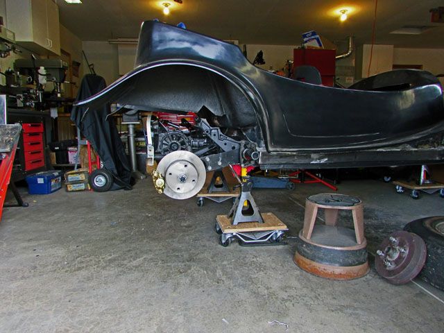
I put the buggy back up on stands today but it will still roll around when I want to. I have it sitting cross-wise in the garage to see if it makes things easier to work on... so far yes!

I did take both of the half-shafts with both of their CV joints off today. I did some checking able axle length and yes, they were under more load than I thought was good so they probably would have given me grief before I got too far out on the dunes. I'm happy now that I did spend the big bucks converting over to bus and the proper axles.
I quit early today as the cold air, off and on rain, causing the pollen to blow. Bad allergies for sure. I didn't take the backing plates off yet and I have decided to replace the two soft brake lines. They would have been OK at full compression as I am keeping the stock bump stop but they are just a bit too short with the notch in the spring plates. When I put them on I thought they were too short at full hang as the bends were just too tight but now I don't think I will take the chance now that I am throwing money at the buggy.
Tomorrow if I get a chance then the backing plates come off and I will try to take torsion bar out of one side so I can check wheel clearance at full compression. I think it would have taken too much time today since I got a late start.
I think pulling the transaxle is going to be a bother with the buggy sitting so high so there might be some lowering the rear of the buggy in order to get the transaxle out safely... for it and me. With it as high as it is it sure is easy to work under.
Lee
-
Ol'fogasaurus
- Posts: 17881
- Joined: Mon Nov 13, 2006 10:17 pm
Re: Ol'fogasaurus black buggy
I did some work in the garage today. I checked the pre-load and it was 20° so I am OK on that.
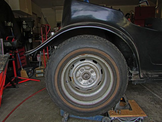
While I had the trailing arms disconnected from the spring plates to check pre-load I decided to check travel. The tires that are on there are 29" tall tires. Both my paddles and my Desert Trax tires are 30". If the diameter they give includes the paddles, if not then I would add about an inch for the paddles themselves. The bump stops here were slightly in compression but not too much.
I also started on converting to the disc brakes. I got the kit with the cast caliper mounts not the stamped steel ones. The stub axles for the bus CVs are in place in the pictures.
Lee

While I had the trailing arms disconnected from the spring plates to check pre-load I decided to check travel. The tires that are on there are 29" tall tires. Both my paddles and my Desert Trax tires are 30". If the diameter they give includes the paddles, if not then I would add about an inch for the paddles themselves. The bump stops here were slightly in compression but not too much.

I also started on converting to the disc brakes. I got the kit with the cast caliper mounts not the stamped steel ones. The stub axles for the bus CVs are in place in the pictures.
Lee
-
Ol'fogasaurus
- Posts: 17881
- Joined: Mon Nov 13, 2006 10:17 pm
Re: Ol'fogasaurus black buggy
A holding spot for some information.
On the blue buggy I made the Napoleon's hat I used one from a rusted out commercial body lift that was a slip over style. Iguana makes his unit to sit on top of the Napoleon's hat which is going to be stronger. The style he has and the cast units as far as I could find were not available at the time. The other thing I did was to bring the rear cross piece all the way over to the edge of the body mount tunnel which I think should be stronger than the way I did it on the black buggy when I ran the side rails all the way to the rear of the pan. Another thing that happened was that on the blue buggy the rectangular tube i got had the seam up high in the 3 inch high wall.
On the black buggy the tube I got, but didn't notice at the time, had the seam down the center of the three inch high wall and it gave me fits. Since the seam had to be on the inside radius that when the kerfs were welded and I got to welding on the seam and then in clamped it the seam shrunk. I finally figured out how to get around the problem I still didn't trust it so I added localized doublers in the area which I should have done on the first body lift. To be honest I did not learn how to weld until I was into my 60s and don't weld enough to be really good at it.
The rear cross piece as I said above was done a bit differently. Both the black and the blue buggy joins to the side rails were gusseted thoroughly.
The Napoleon's hat was constructed differently because I wasted hydraulics. I was going Street only but now I would probly do it a lot differently now. The no hood opening was the limitation which could have been done.
The other thing I did differently was the tube going down the body mount tunnel. I did put in crush sleeves at hotrodsupply's advice.
-
Ol'fogasaurus
- Posts: 17881
- Joined: Mon Nov 13, 2006 10:17 pm
Re: Ol'fogasaurus black buggy
Started working on the brake for the left side but doesn't want to bolt on cleanly. I think at least one, if not a couple of the holes in the cast bracket is off just enough that only one of the axle seal cover bolts will thread in easily. I am taking it in to where I got the kit for replacement as I shouldn't have to fit the holes and possible get a potentually sloppy fit. They are so close but just not there. The other side was a no sweat installation.
Lee
Lee
-
Ol'fogasaurus
- Posts: 17881
- Joined: Mon Nov 13, 2006 10:17 pm
Re: Ol'fogasaurus black buggy
Thought you might be interested.
I think I mentioned that the brake bracket and caliper on the passenger side went on with no problems but the driver's side caliper bracket did not want to bolt in place. I could get one bolt in place with not too much problem and two more felt like they were being cross-threaded but the last bolt was a not-even-close thing. I pulled the caliper off and checked the bolts in the threads on the trailing arm and no problems I reinstalled the bracket in another direction just to check to see if it was the bolts and not really any change that way.
So... today I took it back up to where I got the kit. We played with it for a while and the guy got the same results as I did and was puzzled. He finally lifted the bracket up off the trailing arm and got the bolts to go in the holes in the trailing arm but when he dropped the bracket it would not go over the centering piece in the trailing arm.
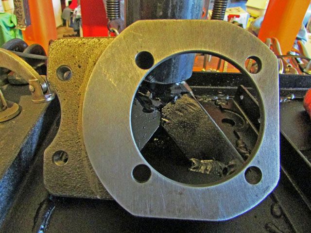
This is the bracket. I didn't take a good picture but if you look closely on the left side the edge margin on the holes to the big hole is shy some "meat". The difference between the opposite holes divided by ~ by 2 is about the ~ the amount of miss-match of where the big hole is for it fitting correctly. If I "fitted" the mounting holes then the caliper would not be sitting "as designed" on the rotor and there might be some other problems that could come up.
He contacted the supplier and the left and right side brackets' are identical/the same so that wasn't part of the problem (we checked for that too). I would have thought that the "go/no-go" jig/checking fixture would have caught this so there must have been "a bad day at black rock"!
The new part should be here this week or early next week.
-
Ol'fogasaurus
- Posts: 17881
- Joined: Mon Nov 13, 2006 10:17 pm
Re: Ol'fogasaurus black buggy
I got some time in the garage today after getting the disc brake caliper mounting bracket problem fixed. I replaced the stock brake flex line with a couple of 1” longer units which are going to work well and not have the flex line stretched tight at full hang.
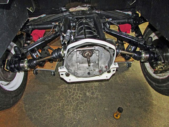
I also got the transaxle pulled from the car. Fairly simple and was able to do it by myself without taking the buggy down from the stands although I did put the wheels on it for a just-in-case.
When doing the research for putting the new drive flange on the transaxle I noticed some things that were recommended so they were ordered. Today I did one side of the transaxle taking pictures of each step. I hope it isn’t too much but it is going to be there for the record when I do the other side of the transaxle.
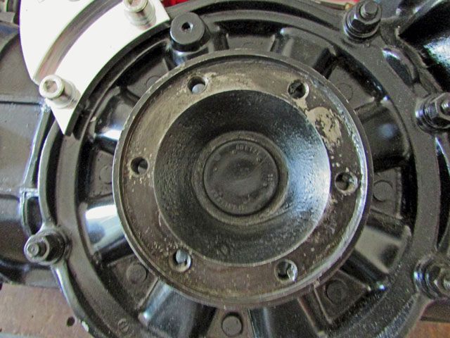
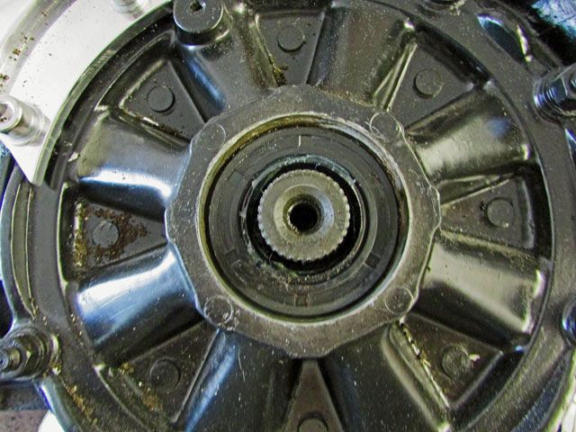
This is the area that will be changing on the stock bug transaxle. First the dust cover on the old drive axle must be removed. It is a soft cover so using a long screwdriver I was able to worry the dust cover off.
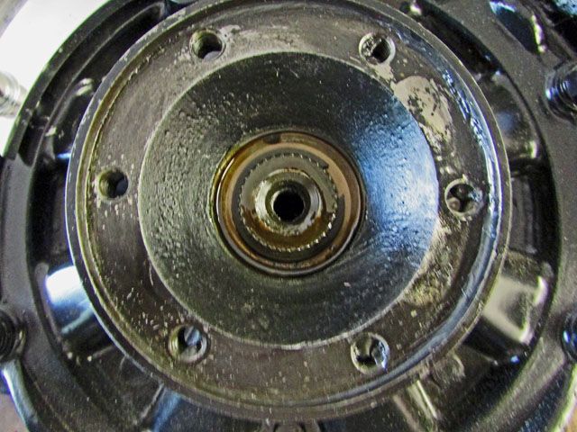
This is what you find under the cover. Using snap-ring pliers you have to remove the C-clip from its slot.
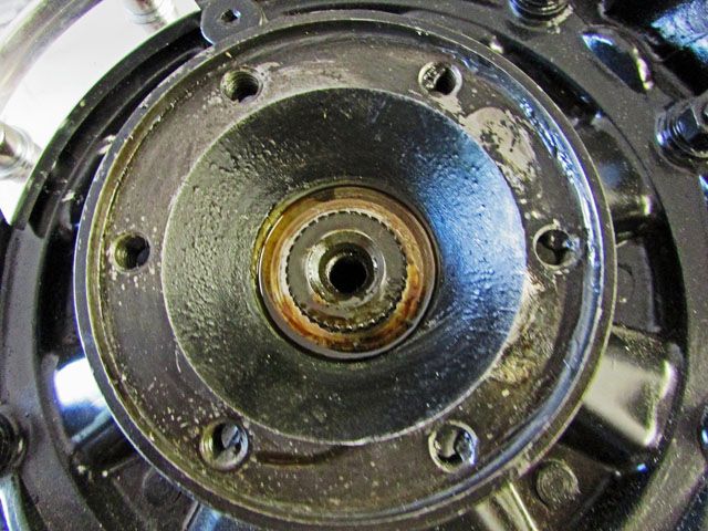
The C-clip is removed here. The white, I am not sure what it really is but it has to be cleaned off.
Using a long pry bar type of driver I gently lifted the drive flange up and out of the splines. There was more of the white stuff which is on the seal I cleaned off before going to the hard part of the job; removing the seal.
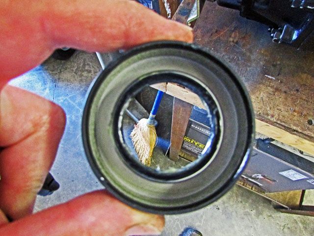
I was told to drill a small hole in the seal, put a screw in it then, using a slide hammer attached to the screw work the seal out. OK, I am not real comfortable about drilling holes where the shaving can drop into the transaxle. I went down to HF which is close by and bought one of their $21 small slide hammers which I was told would work.
I did drill the hole making sure I cleaned the area every few second (to get rid of drill chips so they didn’t drop down when the seal came loose. The grease on the drill bid did it job so when the small drill bit went through the seal I stopped quickly, cleaned the area and put a 1” pointed screw in and wound it is a bit.
One of the accessories on the slide hammer was a foot with a slot in it. I put it on the slide hammer and slipped it around the screw head the Whacko… nothing! I tried it again with the same results so finally I got a good angle at things and jerked the weight up and… the seal and screw disappeared… Whaaa! (I did find the pair later not too far away).
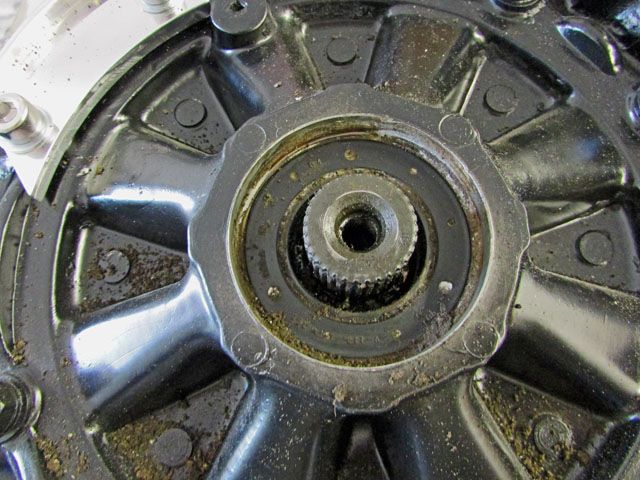
You’ve hit bottom here. Clean the area up making sure that all the grit and chips (if any of either are around) and you are ready to reverse the fix.
This is the new seal. Put a bit of grease on the rubber area where they drive will go through. I added a bit to the bottom also. This is what keeps the internal fluid from coming out of the side of the transaxle so it is a good time to replace it.
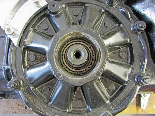
This is the new seal driven in place. I could mic the depth so you know just have deep you have to drive it in. I did not find the driving of the seal in to be a fun or easy job like the rest of the change over is.
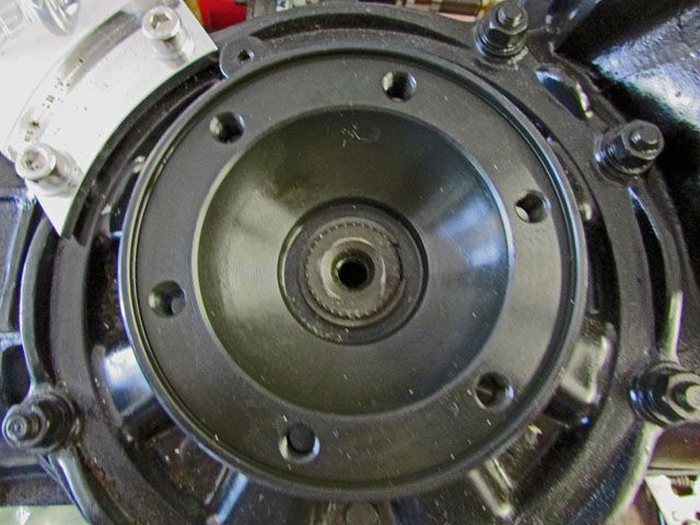
Gently insert the new drive flange in. If it gets a bit balky or testy you may say “if you please” then gently assist it in. Mine hung for a second then when got past a short section of the splines then dropped in.
Now add the C-clip back in place. I used a new one which wasn’t expensive so I know there shouldn’t be a problem with it. I did lightly tap it down using a socket so I knew the drive flange and the C-clip were all the way down and in place.
This shows the flange and C-clip in place so now it is time for the dust boot. It can be installed using your fingers.
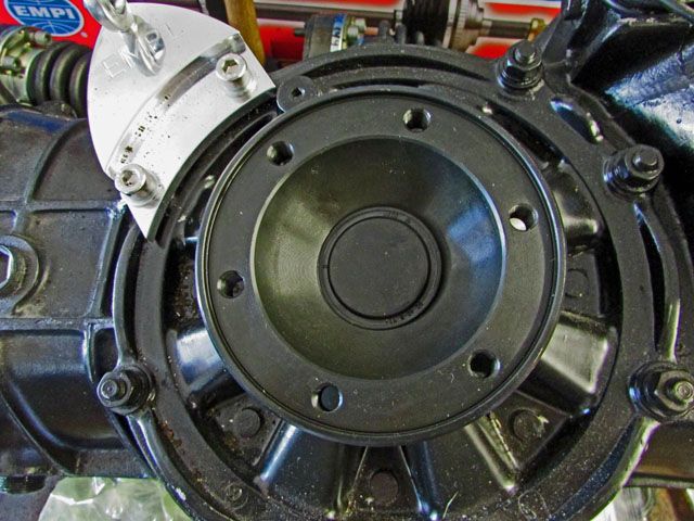
And… wha-la… it is done. Now onto the other side when I get time in the garage.
Lee
I also got the transaxle pulled from the car. Fairly simple and was able to do it by myself without taking the buggy down from the stands although I did put the wheels on it for a just-in-case.
When doing the research for putting the new drive flange on the transaxle I noticed some things that were recommended so they were ordered. Today I did one side of the transaxle taking pictures of each step. I hope it isn’t too much but it is going to be there for the record when I do the other side of the transaxle.

This is the area that will be changing on the stock bug transaxle. First the dust cover on the old drive axle must be removed. It is a soft cover so using a long screwdriver I was able to worry the dust cover off.

This is what you find under the cover. Using snap-ring pliers you have to remove the C-clip from its slot.

The C-clip is removed here. The white, I am not sure what it really is but it has to be cleaned off.

Using a long pry bar type of driver I gently lifted the drive flange up and out of the splines. There was more of the white stuff which is on the seal I cleaned off before going to the hard part of the job; removing the seal.
I was told to drill a small hole in the seal, put a screw in it then, using a slide hammer attached to the screw work the seal out. OK, I am not real comfortable about drilling holes where the shaving can drop into the transaxle. I went down to HF which is close by and bought one of their $21 small slide hammers which I was told would work.
I did drill the hole making sure I cleaned the area every few second (to get rid of drill chips so they didn’t drop down when the seal came loose. The grease on the drill bid did it job so when the small drill bit went through the seal I stopped quickly, cleaned the area and put a 1” pointed screw in and wound it is a bit.
One of the accessories on the slide hammer was a foot with a slot in it. I put it on the slide hammer and slipped it around the screw head the Whacko… nothing! I tried it again with the same results so finally I got a good angle at things and jerked the weight up and… the seal and screw disappeared… Whaaa! (I did find the pair later not too far away).

You’ve hit bottom here. Clean the area up making sure that all the grit and chips (if any of either are around) and you are ready to reverse the fix.

This is the new seal. Put a bit of grease on the rubber area where they drive will go through. I added a bit to the bottom also. This is what keeps the internal fluid from coming out of the side of the transaxle so it is a good time to replace it.

This is the new seal driven in place. I could mic the depth so you know just have deep you have to drive it in. I did not find the driving of the seal in to be a fun or easy job like the rest of the change over is.

Gently insert the new drive flange in. If it gets a bit balky or testy you may say “if you please” then gently assist it in. Mine hung for a second then when got past a short section of the splines then dropped in.
Now add the C-clip back in place. I used a new one which wasn’t expensive so I know there shouldn’t be a problem with it. I did lightly tap it down using a socket so I knew the drive flange and the C-clip were all the way down and in place.
This shows the flange and C-clip in place so now it is time for the dust boot. It can be installed using your fingers.

And… wha-la… it is done. Now onto the other side when I get time in the garage.
Lee
-
cbeck
- Posts: 243
- Joined: Tue Oct 20, 2015 5:17 pm
Re: Ol'fogasaurus black buggy
There is a guy over on tos having issues with his aftermarket arms, sounds like his inner bearing area is machined incorrectly. His stub is hitting the housing before becoming fully inserted. Has the same brake bracket as you and the rotor does not line up with the caliper.
-
Ol'fogasaurus
- Posts: 17881
- Joined: Mon Nov 13, 2006 10:17 pm
Re: Ol'fogasaurus black buggy
The one side I have installed seems to be OK or at least as I remember anyway. I'll take a better look when I can get back out to the garage. Everything is parallel, or was when I was adjusting things anyway.
Thanks for the alert!
Lee
Thanks for the alert!
Lee
-
Ol'fogasaurus
- Posts: 17881
- Joined: Mon Nov 13, 2006 10:17 pm
Re: Ol'fogasaurus black buggy
I just got in from doing the other side and putting the transaxle back in the car and hooking up the clutch. If I had of remember where I put the four bolts and two nuts for the front mount it all would have been done in about 1/2 an hour. The second side went a lot faster than the first side but then I wasn't taking pictures either  .
.
Lee
Lee
-
Ol'fogasaurus
- Posts: 17881
- Joined: Mon Nov 13, 2006 10:17 pm
Re: Ol'fogasaurus black buggy
Heading to the dunes in the morning for the fourth but I did get some time in the garage today.
The half-shafts and CVs are now in the buggy but only finger tight until the new Bus CV bolt washer come in. The CVs fit into the new transaxle drive flange and stub axles very snugly. The bolt also threaded into the drive flange and the stub axles very smoothly.
I then got the Truss bar out of the box and OMG; mothing like I imagined and nothing fit the way I imagined it would. I was really confused especially there were no instructions in the box... only stuffing paper and parts. The spherical rod ends came in both left and right hand threads as well as did the jam nuts but there were too many of them and they didn't fit where I expected them to; the quality looked to be pretty good. I got out the catalogue and looked and it didn't make sense to me (prejudiced thinking on my part now that I understand what was going o)n.
I called Doug and Autovice and since he had never done one he looked on line and started to explain what was going on to me. I would never have thought of doing it that way but it should work... I guess. Crapunzel it was confusing until a dim light started to burn and I started to understood why it was done that way.
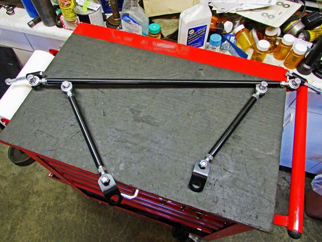
Since I probably wouldn't have remembered (maybe I would but not taking any chances) what was going to have to be done I put it together and left in on one of my benches. In order to make the bend that the shocks sit at on the shock mount they are using a spherical rod ends at each end of the long tube. The long tubes connects to the tabs on the mount that the shock bolts go through and hangs down. The adjustable rods that are at an angle connect to the pans transaxle mount. The bracket has a big hole for the transaxle mount bolt to go through. Once every thing has been adjusted up tight and jam nutted in place they should to work against each other and make a tight, sturdy mount. I guess it is supposed to be pretty strong but I will hopefully find out before too long.
One more step semi-finished.
Lee
It is better than what is there now I guess.
-
dustymojave
- Posts: 2313
- Joined: Mon Dec 01, 2008 9:08 pm
Re: Ol'fogasaurus black buggy
Those kaefer bar kits are designed to work with stock style bellhousing mounts. The tabs for the lower ends of the diagonal braces may be rather difficult to fit. I suggest trying to use the 3/8" holes in the steel motor mount that you have. That's what those holes are for.
I'll have to check back through your thread to see if there is a view of the mount from behind the car.
I'll have to check back through your thread to see if there is a view of the mount from behind the car.
Richard
Lake LA, Mojave Desert, SoCal
Speed Kills! but then...So does OLD AGE!!
Tech Inspection: SCCA / SCORE / HDRA / ARVRA / A.R.T.S. OffRoad Race Tech - MDR, MORE, Glen Helen BajaCup
Retired Fabricator
'58 Baja with 955K Miles and counting
Lake LA, Mojave Desert, SoCal
Speed Kills! but then...So does OLD AGE!!
Tech Inspection: SCCA / SCORE / HDRA / ARVRA / A.R.T.S. OffRoad Race Tech - MDR, MORE, Glen Helen BajaCup
Retired Fabricator
'58 Baja with 955K Miles and counting