The solution to a problem you could run into: http://www.shoptalkforums.com/viewtopic ... 8&t=137895
Lee
Basic Off-road Ball-Joint Beam rebuild PT 2 starts on p. 13
-
Ol'fogasaurus
- Posts: 17881
- Joined: Mon Nov 13, 2006 10:17 pm
-
Ol'fogasaurus
- Posts: 17881
- Joined: Mon Nov 13, 2006 10:17 pm
Re: Very Basic Off-road Ball-Joint Beam rebuild
Between being lazy, Honey-dos and other distractions, I have not posted for a while. I am still doing some clean-up work on the stops as the flaring I was having problems with did go under the weld so I am seeing if it did go to the gussets and then will weld those holes shut.
This is a lot of learning for me as I go through this build so I am trying to get all the information posted that I can.
I bought a pair of what I understood to be (and still are as far as I have been able to discern) a pair of Thing trailing arms and spindles for the 3 ½ inch suspension lift. Two of the BJs were missing and the other two were either frozen in position or just about so. I had one BJ pressed out by a machine shop with the guy showing me how to do it and the other one I pressed out; both of them were very stuck and I ended up heating the trailing arm boss up a bit and driving the BJ with hammer and socket to get it moving. As it was it took 12.5 tons of pressure on the first one done by a shop and the one I did was about the same (I don’t have a gauge on my 20 ton shop press); so now it is about time I started pressing the new ball-joints (BJs) in; since this is my first attempt at it I will share what I have learned so far.
The Thing upper trailing arms are about the same as standard type I trailing arms so you can use the type I trailing arms to use the stronger Thing upper BJs if you want. The Thing and type I ball-joint press in from the same direction so they will interchange; the difference between the two ball-joints being the size of the stud with the Thing stud is bigger in diameter (probably for the bung on the Thing spindle being mounted lower causing more load on the ball-joint than the sedan spindle would have).
This also requires a different adjuster for alignment. New Thing adjusters are non existent from what I have been told. I was also told that you can use a stock sedan adjuster but it has to be reamed to the larger Thing adjuster size (ball-joint stud size). The new sedan replacement adjusters are now off-set more than OEM (to accommodate the lowered suspensions’ now in vogue) so it is probably not going to be a good idea to use the off-set adjusters that I have seen for sale lately.
One other thing, the two arms look identical but there are a couple of things to know; e.g., the left arm marking is slightly different than the right arm. On the left arm the notch for BJ alignment is only found on one side of the boss as compared to the marking for the ball-joint on the right arm which is on both sides of the boss. Another thing to know is that the grub screw on the left (the driver’s side) faces up while on the right side (the passenger side), the grub screw faces down. I checked this with a spare BJ beam and that seems to be true.
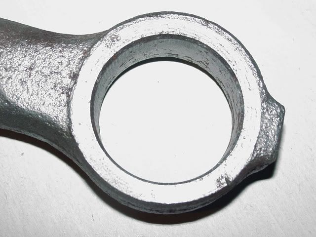
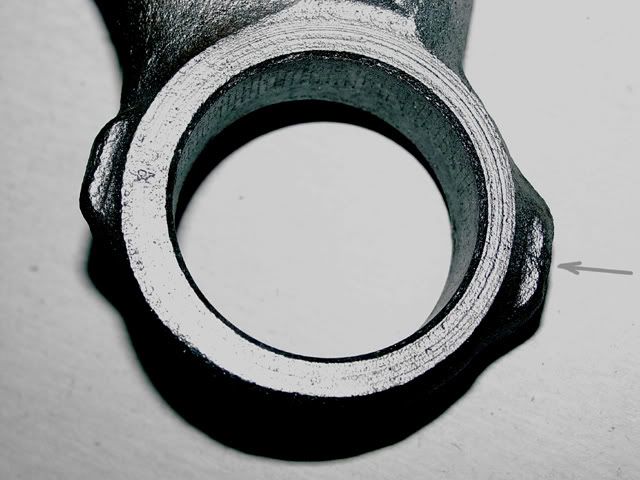
This is the underneath side of the left upper trailing arm; in the lower right of the picture you can see a “Vee” shaped notch formed into the outside edge of the socket for the ball-joint. This notch is common in all the arms I have so look for the notch. I understand some companies use dots and some have scribed lines so if the marks are starting to fade, use a punch and highlight the alignment marks.
The two upper arms use the same ball-joint and the ball-joints have two notches, 180 from each other; the ball-joint can be installed with either notch aligning with the mark on the boss. This alignment allows the ball-joint to be properly aligned for suspension change but still allows some additional movement if and when required. The alignment of the ball joint allows for some Ooo-oo’s but not much so be careful. If you goof and press it in the wrong side or make too much of an Ooo-ooo $#!t then if you are extremely careful and EXTREAMLY lucky you may be able to press the joint out and reuse it… but don’t count on it. I would be careful and not do it wrong in the first place.
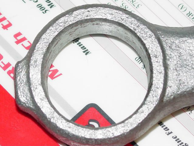
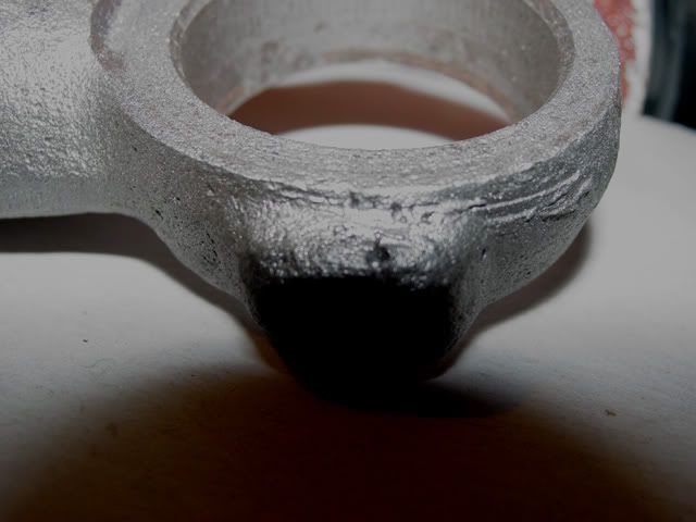
This is the other side of the boss on the upper LH/driver’s side trailing arm. Notice that there are no marks for ball-joint alignment.
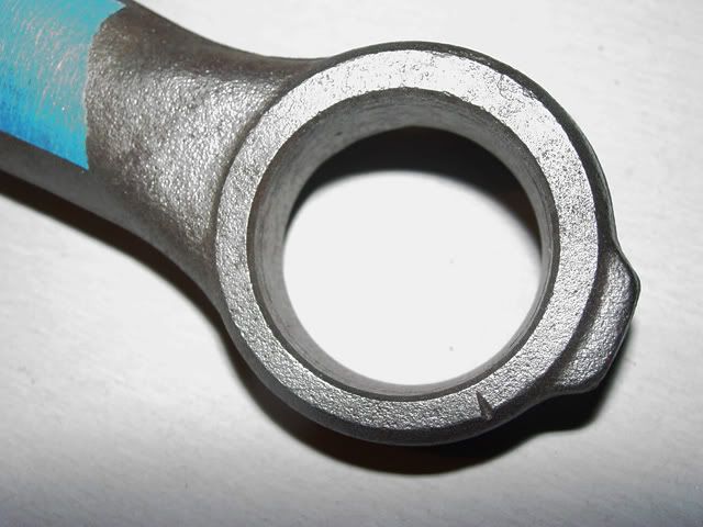
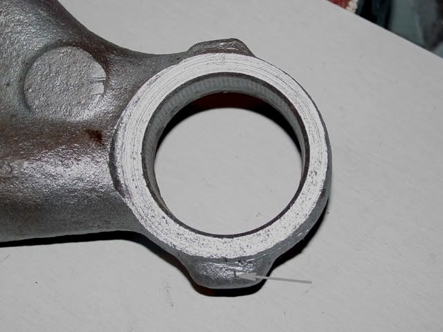
The RH/passenger side ball-joint aligning notches are shown in the next two pictures. They all look a like the same picture but are not.
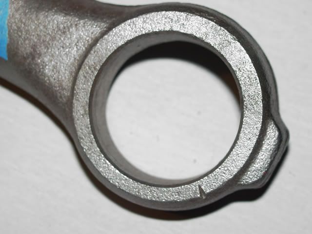
They look almost the same don’t they? I suspect if you had to then this arm could be used on either side.
I have a tendency to get very focused when doing some things so I take a few extra precautions to make sure I don’t over focus and make an Ooo-oo or an AW-$#it ( varying degrees of the same mistake).
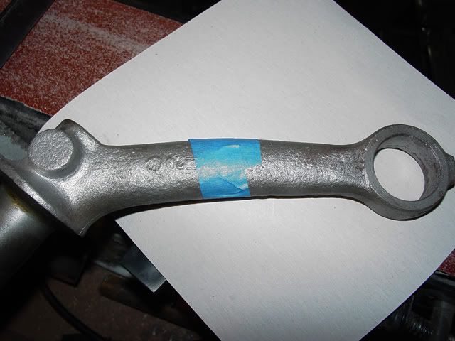
This is the left arm and I put a piece of tape around it. In engineering, if there are opposite sides (e.g., in an airplane) the left hand part (or as shown part) is the odd number so I added one tape strip…
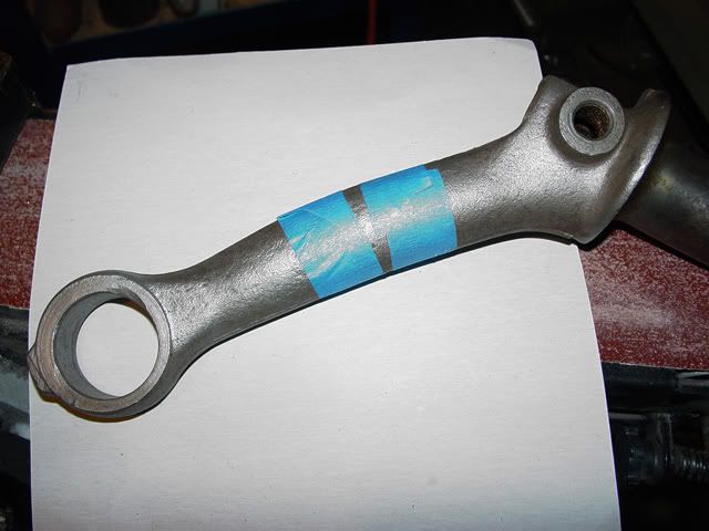
… so this means that this is the right side because of two stripes.
I also go one step farther and add a single strip of tape along the bottom of the arm to denote which side will go down (no picture here) and the ball-joint is pressed in with the tape facing up. Just another step in idiot proofing… which I can prove doesn’t work.
This should confuse you long enough for me to do some actual work… before too long anyway.
If I got anything wrong (and I have asked a lot of question before I posted this) please correct me soon as I am chomping at the bit to start loading the ball-joints in the trailing arms!
Lee
This is a lot of learning for me as I go through this build so I am trying to get all the information posted that I can.
I bought a pair of what I understood to be (and still are as far as I have been able to discern) a pair of Thing trailing arms and spindles for the 3 ½ inch suspension lift. Two of the BJs were missing and the other two were either frozen in position or just about so. I had one BJ pressed out by a machine shop with the guy showing me how to do it and the other one I pressed out; both of them were very stuck and I ended up heating the trailing arm boss up a bit and driving the BJ with hammer and socket to get it moving. As it was it took 12.5 tons of pressure on the first one done by a shop and the one I did was about the same (I don’t have a gauge on my 20 ton shop press); so now it is about time I started pressing the new ball-joints (BJs) in; since this is my first attempt at it I will share what I have learned so far.
The Thing upper trailing arms are about the same as standard type I trailing arms so you can use the type I trailing arms to use the stronger Thing upper BJs if you want. The Thing and type I ball-joint press in from the same direction so they will interchange; the difference between the two ball-joints being the size of the stud with the Thing stud is bigger in diameter (probably for the bung on the Thing spindle being mounted lower causing more load on the ball-joint than the sedan spindle would have).
This also requires a different adjuster for alignment. New Thing adjusters are non existent from what I have been told. I was also told that you can use a stock sedan adjuster but it has to be reamed to the larger Thing adjuster size (ball-joint stud size). The new sedan replacement adjusters are now off-set more than OEM (to accommodate the lowered suspensions’ now in vogue) so it is probably not going to be a good idea to use the off-set adjusters that I have seen for sale lately.
One other thing, the two arms look identical but there are a couple of things to know; e.g., the left arm marking is slightly different than the right arm. On the left arm the notch for BJ alignment is only found on one side of the boss as compared to the marking for the ball-joint on the right arm which is on both sides of the boss. Another thing to know is that the grub screw on the left (the driver’s side) faces up while on the right side (the passenger side), the grub screw faces down. I checked this with a spare BJ beam and that seems to be true.
This is the underneath side of the left upper trailing arm; in the lower right of the picture you can see a “Vee” shaped notch formed into the outside edge of the socket for the ball-joint. This notch is common in all the arms I have so look for the notch. I understand some companies use dots and some have scribed lines so if the marks are starting to fade, use a punch and highlight the alignment marks.
The two upper arms use the same ball-joint and the ball-joints have two notches, 180 from each other; the ball-joint can be installed with either notch aligning with the mark on the boss. This alignment allows the ball-joint to be properly aligned for suspension change but still allows some additional movement if and when required. The alignment of the ball joint allows for some Ooo-oo’s but not much so be careful. If you goof and press it in the wrong side or make too much of an Ooo-ooo $#!t then if you are extremely careful and EXTREAMLY lucky you may be able to press the joint out and reuse it… but don’t count on it. I would be careful and not do it wrong in the first place.
This is the other side of the boss on the upper LH/driver’s side trailing arm. Notice that there are no marks for ball-joint alignment.
The RH/passenger side ball-joint aligning notches are shown in the next two pictures. They all look a like the same picture but are not.
They look almost the same don’t they? I suspect if you had to then this arm could be used on either side.
I have a tendency to get very focused when doing some things so I take a few extra precautions to make sure I don’t over focus and make an Ooo-oo or an AW-$#it ( varying degrees of the same mistake).
This is the left arm and I put a piece of tape around it. In engineering, if there are opposite sides (e.g., in an airplane) the left hand part (or as shown part) is the odd number so I added one tape strip…
… so this means that this is the right side because of two stripes.
I also go one step farther and add a single strip of tape along the bottom of the arm to denote which side will go down (no picture here) and the ball-joint is pressed in with the tape facing up. Just another step in idiot proofing… which I can prove doesn’t work.
This should confuse you long enough for me to do some actual work… before too long anyway.
If I got anything wrong (and I have asked a lot of question before I posted this) please correct me soon as I am chomping at the bit to start loading the ball-joints in the trailing arms!
Lee
-
Steve Arndt
- Posts: 7420
- Joined: Sat Mar 10, 2001 12:01 am
Re: Very Basic Off-road Ball-Joint Beam rebuild
Amazing post. This will come in very handy. Sticky post maybe since so many threads are about thing/lift spindles.
-
Ol'fogasaurus
- Posts: 17881
- Joined: Mon Nov 13, 2006 10:17 pm
Re: Very Basic Off-road Ball-Joint Beam rebuild
Well, I got some time in the garage today. I was able to get the temperature in the garage to over 50° and the rest of the family was gone traipsing around. I finally got around to taking the chance of doing something wrong and went for pushing the ball-joints in the upper trailing arms. I got both of them done and it turned out that as usual, the setting of it up was the hard part… that and getting up the gumption of start the actual job. I had done a lot of asking around on how to do it and what could go wrong so I have actually been ready for a while, but…
Be warned, this is going to have a lot of pictures as I decided to go basic on the instructions.
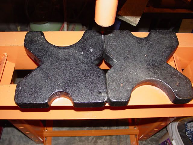
I first started by putting down the platen’s (not the right name I am pretty sure) so that I not only had something to press against but that would allow the trailing arm boss to sit flat and was perpendicular to the press itself. Trying most of the hole positions (the ball-joint has a protrusion that I wasn’t sure if it would come all the way though the arm or not) so I ended up using this combination.
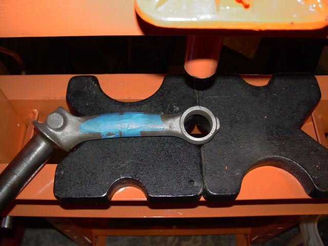
I was able to get all the parts together and lay flat after I shimmed up the part that goes into the beam. Again, it is the setup that makes life easier.
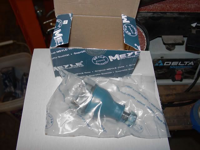
This is the brand of ball-joint I could get locally (I try to support local as much as I can). This is a Thing (Type 181) upper ball-joint. It comes in a sealed bag which I was pleased of and it has a cover over the joint to protect it which I was more than pleased to see.
This is the joint and it’s cover.
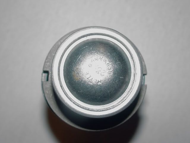
This is the bottom of the ball-joint and the protrusion I was talking about.
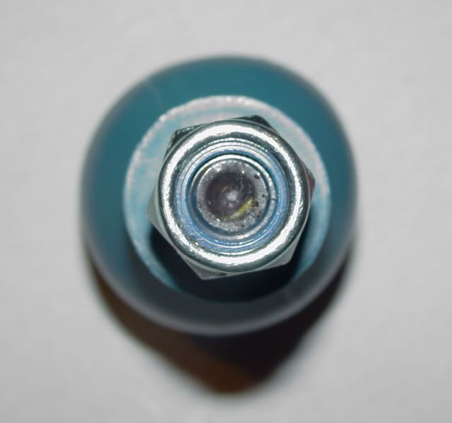
This is looking down at the top of the ball-joint. Notice that there is an accommodation in the stud for an Allen head wrench used when aligning the front end.
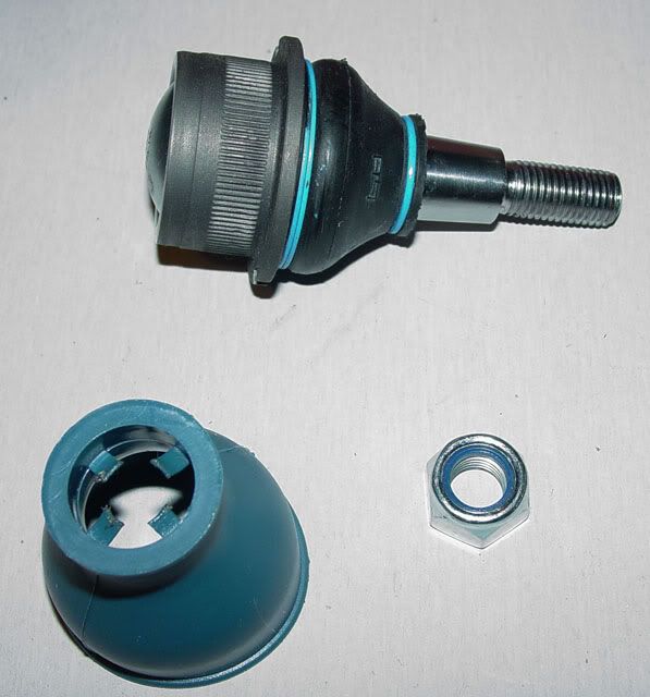
The assembly w/protective cover shown.
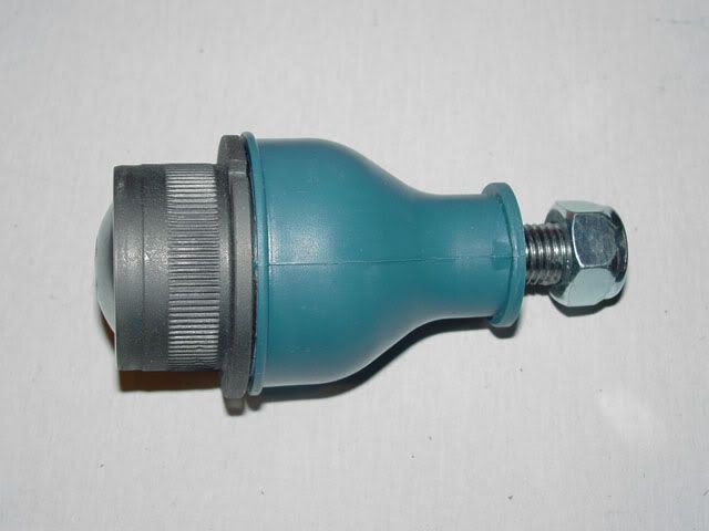
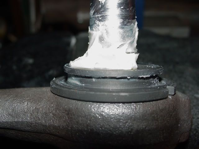
OK, now we are getting into the trouble area. This is the business end, the part that goes into the trailing arm boss but there is not enough room to safely press on the flanges or without damaging the boot so the boot much come off (at least in my case).
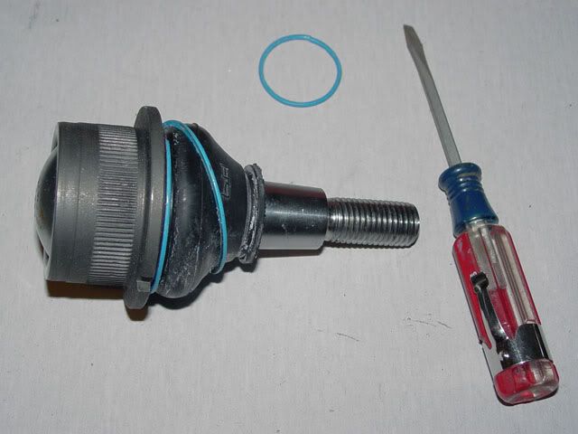
The upper ring came off very easily but the lower ring that holds the boot on was a different matter. You have to unwind it without damaging the boot and it will mostlikely fight you start to finish so be patient and work slow and keep your hands clean as the grease in there is real slip’em-slide’em stuff!.
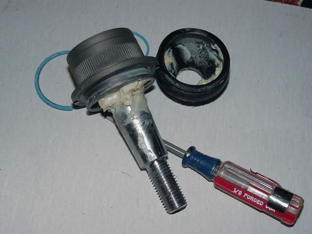
This is the ball-joint with the boot off. You can see the ridge and channel that the clamp for the boot to sit in.
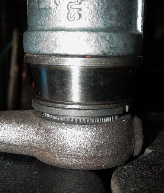
The next few pictures are of the stack of spaces I needed to get above the stud to start pressing it in. Notice the aligning notch in the ball-joint and the mark on the trailing arm boss that I talked about in the last installment of this adventure.
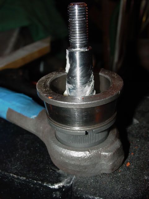
This is an old bearing race I was give that fit on the land (never throw anything away as you never know when it will come in handy). It turned out to be a perfect fit as the inside diameter was just over a net fit.
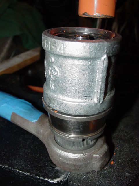
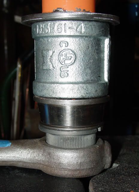
The next level was a 1 ¼ X 1 ¼ X 2” pipe join. It fit nice on the old bearing race and just barely topped the end of the stud.
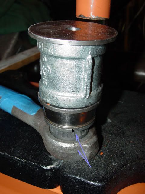
The bottom of the shop press is ~ 1 ¼ so I turned a piece of ¼ flat stock to cover the hole and it worked great… so far.
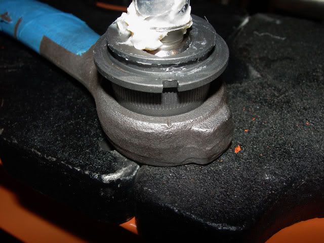
I put the arrows on to show the relationship of the notches in the ball-joint and the mark on the trailing arm bung. The mark on the bung should be centered in the notch in the ball-joint; the notch is more of a window to sight the mark in. Aligning those two features aligns the ball-joint’s travel with the alignment of the trailing arms as the move up and down in their arc. The idea is to be as close centered as you can but there is some leeway (not much but some) too.
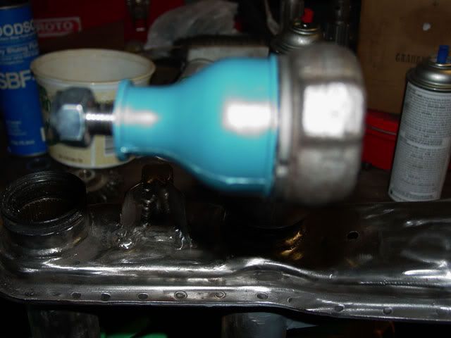
I slid the bottom of the press around as well as the platens to get the ball-joint and trailing arm aligned and then… (hold your breath)… pumpy-pumpy, squeaky-squeaky and nasty things started happening...; it started pressing the joint in in a controlled violence of sort. Notice the notch in the ball-join and the mark on the trailing arm stud.
pumpy-pumpy, squeaky-squeaky
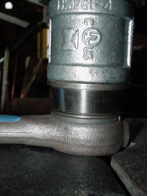
pumpy-pumpy, squeaky-squeaky… aaah (shush), I think it is there as it is getting too hard to do any more pumping. Got a flashlight and looked, sure enough it was home.
I pulled the spacers off and lifted the arm up had this is what I had done.
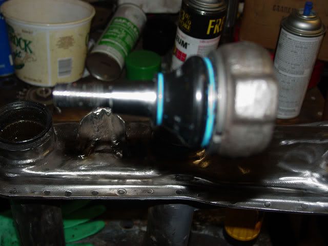
I put the trailing arm in the beam to check to see if I did it correctly,,, looks gud!
I put the protective boot on also, It looks like when I paint the arm I can leave the boot on to stop the over spray on the ball-joint boot.
Now I have to press the lower ball-joint.
Lee
Edit, I forgot to add that you probably don't need a 20 ton press to install the ball-joints but it does make it easy. I would use one to press the joints out though as they can be tough somethimes. It was very smooth pressing them in and not what I expected but after seeing it done before, that is what it looked like... smooth. Lee
Be warned, this is going to have a lot of pictures as I decided to go basic on the instructions.
I first started by putting down the platen’s (not the right name I am pretty sure) so that I not only had something to press against but that would allow the trailing arm boss to sit flat and was perpendicular to the press itself. Trying most of the hole positions (the ball-joint has a protrusion that I wasn’t sure if it would come all the way though the arm or not) so I ended up using this combination.
I was able to get all the parts together and lay flat after I shimmed up the part that goes into the beam. Again, it is the setup that makes life easier.
This is the brand of ball-joint I could get locally (I try to support local as much as I can). This is a Thing (Type 181) upper ball-joint. It comes in a sealed bag which I was pleased of and it has a cover over the joint to protect it which I was more than pleased to see.
This is the joint and it’s cover.
This is the bottom of the ball-joint and the protrusion I was talking about.
This is looking down at the top of the ball-joint. Notice that there is an accommodation in the stud for an Allen head wrench used when aligning the front end.
The assembly w/protective cover shown.
OK, now we are getting into the trouble area. This is the business end, the part that goes into the trailing arm boss but there is not enough room to safely press on the flanges or without damaging the boot so the boot much come off (at least in my case).
The upper ring came off very easily but the lower ring that holds the boot on was a different matter. You have to unwind it without damaging the boot and it will mostlikely fight you start to finish so be patient and work slow and keep your hands clean as the grease in there is real slip’em-slide’em stuff!.
This is the ball-joint with the boot off. You can see the ridge and channel that the clamp for the boot to sit in.
The next few pictures are of the stack of spaces I needed to get above the stud to start pressing it in. Notice the aligning notch in the ball-joint and the mark on the trailing arm boss that I talked about in the last installment of this adventure.
This is an old bearing race I was give that fit on the land (never throw anything away as you never know when it will come in handy). It turned out to be a perfect fit as the inside diameter was just over a net fit.
The next level was a 1 ¼ X 1 ¼ X 2” pipe join. It fit nice on the old bearing race and just barely topped the end of the stud.
The bottom of the shop press is ~ 1 ¼ so I turned a piece of ¼ flat stock to cover the hole and it worked great… so far.
I put the arrows on to show the relationship of the notches in the ball-joint and the mark on the trailing arm bung. The mark on the bung should be centered in the notch in the ball-joint; the notch is more of a window to sight the mark in. Aligning those two features aligns the ball-joint’s travel with the alignment of the trailing arms as the move up and down in their arc. The idea is to be as close centered as you can but there is some leeway (not much but some) too.
I slid the bottom of the press around as well as the platens to get the ball-joint and trailing arm aligned and then… (hold your breath)… pumpy-pumpy, squeaky-squeaky and nasty things started happening...; it started pressing the joint in in a controlled violence of sort. Notice the notch in the ball-join and the mark on the trailing arm stud.
pumpy-pumpy, squeaky-squeaky
pumpy-pumpy, squeaky-squeaky… aaah (shush), I think it is there as it is getting too hard to do any more pumping. Got a flashlight and looked, sure enough it was home.
I pulled the spacers off and lifted the arm up had this is what I had done.
I put the trailing arm in the beam to check to see if I did it correctly,,, looks gud!
I put the protective boot on also, It looks like when I paint the arm I can leave the boot on to stop the over spray on the ball-joint boot.
Now I have to press the lower ball-joint.
Lee
Edit, I forgot to add that you probably don't need a 20 ton press to install the ball-joints but it does make it easy. I would use one to press the joints out though as they can be tough somethimes. It was very smooth pressing them in and not what I expected but after seeing it done before, that is what it looked like... smooth. Lee
-
Lotrat

- Posts: 4975
- Joined: Sat Mar 29, 2008 11:43 pm
Re: Very Basic Off-road Ball-Joint Beam rebuild
I used the same brand ball joints and tie rod ends when I rebuilt my front end. No issues yet. On one outing with the STF boys, I came down hard on the front drivers side and bent my beam. When replacing the beam I noticed that the ball joints on that side were not as tight as the other side. No noticeable up and down movement, but not tight. I replaced them since I had it all apart. I don't run hook stops, so there was nothing to protect them.
So now that you've removed and installed some BJ's, how do you rate that HF press?
So now that you've removed and installed some BJ's, how do you rate that HF press?
-
Ol'fogasaurus
- Posts: 17881
- Joined: Mon Nov 13, 2006 10:17 pm
Re: Very Basic Off-road Ball-Joint Beam rebuild
Since I never have personally had the chance to use anything else I have nothing to compare it to. Also, since this pair of joints went in so easily (no problems) I don't know about it's ability to handle nasty problems either. I added the extra note because things went so well, The only thing I can say it that it performed quite well when pressing that one ball-joint out was about the same as the machinist had with the other joint he pushed out... "WHAM" and everything went flying when the joint let loose. Based on all that, I think it is OK and if it won't handle something then it is time for people who know what they are doing and have insurance to have a go at it. I don't think I would go as low as the 12 ton unit and the6 ton unit is good for pressing wine and fruit leather.
http://www.youtube.com/watch?v=Zt2AY5ZrnIY
http://www.youtube.com/watch?v=-vwacbaO ... re=related
http://www.youtube.com/watch?v=Lw6R3-4Y ... re=related
Lee
http://www.youtube.com/watch?v=Zt2AY5ZrnIY
http://www.youtube.com/watch?v=-vwacbaO ... re=related
http://www.youtube.com/watch?v=Lw6R3-4Y ... re=related
Lee
-
BAJA-IT
- Posts: 2046
- Joined: Tue Oct 07, 2008 5:02 pm
Re: Very Basic Off-road Ball-Joint Beam rebuild
I like to put some anti-seize on the splines of the ball joint when I press them in. They go in smoother and come out easier the next time. I also add a little more grease before I put the boot back on. The bottom ones are the fun ones to do.
BRAT Motorsports #936
Bolt Center: Salt Lake City, Ut
ACE: Air Cooled Engineering, now Black Line Racing
Bolt Center: Salt Lake City, Ut
ACE: Air Cooled Engineering, now Black Line Racing
-
Ol'fogasaurus
- Posts: 17881
- Joined: Mon Nov 13, 2006 10:17 pm
Re: Very Basic Off-road Ball-Joint Beam rebuild
Thanks for the anti-seize tip. Never seen or heard of it being done before but then you usually drop things off and when you come back to pick it up[ holy cow, the auto elves have been busy. Since only the lower BJ’s are left be pressed in from the bottom, it makes sense to do that. We have company coming in and there is a work trip set for the dunes between Christmas and the first if I get to it before next year it will be a miracle if it get done this year. We finally got all the shopping done with one exception and we don’t know if he will be here for gifts or with his family.
I have a bit of clean-up to do on the fix to the rusted part of the shock (anal me) mount and I thought of a trick that may or may not work If it does I will share it, if it doesn’t will, time to start with the other beam assuming it is in better condition. I still haven’t figured out how one beam can be pristine on one side while the other side is a mess like this one is/was. It is only in the one shock tower and as far as I know or can tell, both sides have been covered with body work and not out like a rail might be stored outside. From some marks I have seen, the one shock may have been loose in the hole in the tower so the rubber part of the shock did not seal the hole shut. The only thing I can think of. Welding the towers shut is probably the next step before I finish off the hooks on the trailing arms then go to the adjusters.
I am still looking for the pointed studs for the adjusters that Dusty Mo recommends as I don’t want to chance grinding the ones that came with the kit and goofing that up and ending with nothing.
Lee
-
Ol'fogasaurus
- Posts: 17881
- Joined: Mon Nov 13, 2006 10:17 pm
Re: Very Basic Off-road Ball-Joint Beam rebuild
Boy, did I just get edumacated! The guys on the Thing forum must be splitting a gut on this build.
I had a few minutes between honey-do’s so I decided to press in the lower ball-joints. I open the package and… Oh, Crap, they were the wrong BJs. I called where I got them and the p/n number was correct so I talked to the owner who is also a Thing guy; we couldn’t get on the same page over the phone to figure out what was wrong so I grabbed the parts and the lower arms and headed over to his shop. After about 10 minutes of discussion and his looking at both a bug and Thing beam here is what I found out:
When it is said that ‘the lower ball-joints press in from the bottom’ (which is true), I was under the impression that they pressed though the lower arm which is not true. The do press in from the underside but the ball-joint looks like the upper one and when it is pressed in the stud points down not up like I thought. If you look at the spindles, the arms of the spindles are of a different length with the sedan arms being closer together because the studs on the ball-joint face to the center and the spindle fits in between. On the Thing arms, they are longer since both BJ studs point down and you feed the spindle onto the studs’ bottom up. Silly me!
I will post up some pictures as soon as I can.
Off to do some more Honey-dos'.
Lee
-
BAJA-IT
- Posts: 2046
- Joined: Tue Oct 07, 2008 5:02 pm
Re: Very Basic Off-road Ball-Joint Beam rebuild
That is one of the reason the Thing ball joints are stronger, The ball is getting pushed into the socket on both arms, unlike the bug lower ball joint where it is getting pulled out of the socket.
BRAT Motorsports #936
Bolt Center: Salt Lake City, Ut
ACE: Air Cooled Engineering, now Black Line Racing
Bolt Center: Salt Lake City, Ut
ACE: Air Cooled Engineering, now Black Line Racing
-
Ol'fogasaurus
- Posts: 17881
- Joined: Mon Nov 13, 2006 10:17 pm
Re: Very Basic Off-road Ball-Joint Beam rebuild
I knew it was pushed in from the bottom, I had got the idea somehow it was a through press not facing the other way (down). No harm done and maybe others won't come up wth the wrong impression I had. It brings up other questions though about some new parts that are available on the market now.
Lee
Lee
-
Ol'fogasaurus
- Posts: 17881
- Joined: Mon Nov 13, 2006 10:17 pm
Re: Very Basic Off-road Ball-Joint Beam rebuild
The lower trailing arms bosses are marked different than the upper trailing arms are.
I marked the line that are found on the on the cast pieces on the bosses for the ball-joints. The bosses are cast at an angle and the mark is found on the side were the boss is machined to accept the flange of the ball-joint itself.
On my arms, they were either rusted quite badly (I got them bead blasted so I don’t know) or the casting is so rough that the marks were hard to find. I thought I found the marks but went to my local VW shop to have the marks verified. It took some very strong lights to be able to see the marks on one of the arms.
I then took a center punch and made a mark on the trailing arm to highlight the locating mark. I had tried to file the notches in deeper but a triangular file did not want to do much work on it, Must be a hard material but it did punch easily so that is confusing.
If I get a chance I will try to press the BJ’s in tomorrow.
Lee
-
Ol'fogasaurus
- Posts: 17881
- Joined: Mon Nov 13, 2006 10:17 pm
Re: Very Basic Off-road Ball-Joint Beam rebuild
Since it is looking like I have a full day ahead of me I went ahead and pressed in the lower ball-joints and mounted one in the beam to show the relationship of the two ball-joint studs.
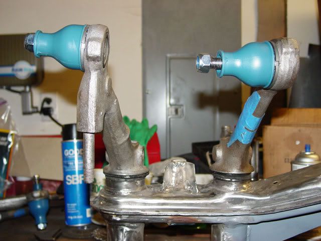
The ball-joints w/protective caps on.
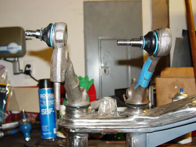
Caps off and showing the lower ball-joint facing down instead of the lower ball-joint facing the upper ball-joint and pressed in from the top of the lower ball-joint.
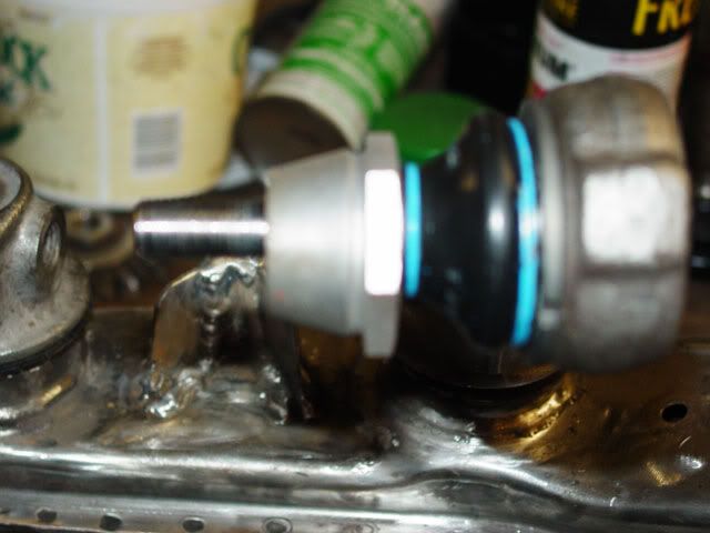
The adjuster for front-end alignment in place.
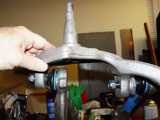
The Thing spindle mounted loosely to show mount on ball-joints.
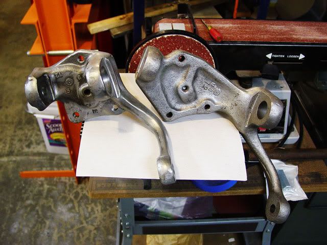
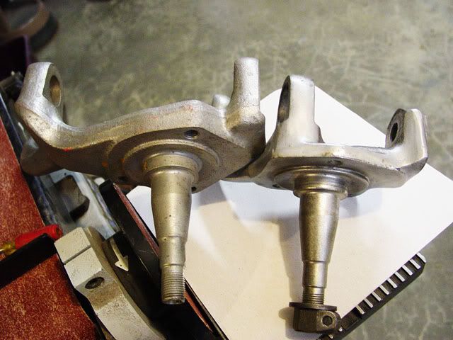
These two pixs shows a Thing and a sedan spindle side by side.
Lee
The ball-joints w/protective caps on.
Caps off and showing the lower ball-joint facing down instead of the lower ball-joint facing the upper ball-joint and pressed in from the top of the lower ball-joint.
The adjuster for front-end alignment in place.
The Thing spindle mounted loosely to show mount on ball-joints.
These two pixs shows a Thing and a sedan spindle side by side.
Lee
-
JUSSUMGUY
- Posts: 2467
- Joined: Sun Jan 18, 2009 12:23 pm
Re: Very Basic Off-road Ball-Joint Beam rebuild
Wow! That is a ton of info. I for one thank you for your efforts.
After looking at the difference between the 2 spindles I have a question. Seems that the Thing spindle raised the location of the upper balljoint, thus changing the distance between the two trailing arms, yet everything steering wise seems to work ok. In the past there was a thread or two talking about using the conversion trailing arms from Bugyzila that allowed the use of kingpin spindles with a balljoint beam. Seemed that there was a consensus of opinion that since the beam spacing of the balljoint was larger than the kingpin spacing that there would be problems. Isn't the Thing spindle by raising the upper balljoint doing essentially the same thing, or am i missing something?
Richard
-
Ol'fogasaurus
- Posts: 17881
- Joined: Mon Nov 13, 2006 10:17 pm
Re: Very Basic Off-road Ball-Joint Beam rebuild
If I understand your questions (and you did ask several questions), the upper part of the spindle that the adjuster and ball-joint fits in sits higher up on the spindle, from the spud, than the stock sedan equivalent sits which is how they get the suspension raised about 2 1/2 inches (the same as moving the spud lower like they do on a raised spindle). This is how they get the spud to sit lower on the spindle which makes the front of the car sit higher. Since the trailing arms work parallel to each other (I think) the longer spindle now has required that the lower ball joint to face the other way than it does on the sedan. With the lower part of the spindle sitting on it (by-the-way, the Thing lower ball-joint is also a bigger diameter than the stock sedan ball- joint is, the same with the upper ball-joint ) by maybe the same 2 ½ (accumulated) inches (I haven’t measured the total thicknesses but if you add the thickness of the trailing arm boss, plus the taper of the ball-joint allowing the spindle to go only so far up the ball-joint and the sedan ball-joint doing the same thing so I am guessing that things even out and the arms stay parallel) that the front of the car sits higher. I haven’t checked it out (but I can as I have another BJ beam stored under my black buggy pan along with a K&L beam (which I can also do some measuring on if you want) but it looks like the arms for the tie-rods sit pretty close to the same as before but I will check (tomorrow?) to make sure.
As far as the BJ and K&L beams go, there is about a ½” difference in spread between the two tubes and while I don’t think it is possible to do a direct swap (again, I don’t know for sure) I think the trailing arms would have to be shaped differently to keep the trailing arms parallel and the spindle sitting correctly though out the arc of travel when cycling the suspension. Someone would have to lay it out or someone with access to a good CAD program that would allow animation could figure this out quite quickly.
Does this answer what you wanted or did I miss the boat?
Lee