Ol'fogasaurus black buggy

Offroad VW based vehicles have problems/insights all their own. Not to mention the knowledge gained in VW durability.
Ol'fogasaurus
Posts: 17756
Joined: Mon Nov 13, 2006 10:17 pm

Re: Ol'fogasaurus black buggy

Post by Ol'fogasaurus »

http://www.shoptalkforums.com/viewtopic ... 1&t=148956 This is an idea for the front suspension that I am playing with for the black buggy but, assuming I go with it, will probably try it out as a complete beam switch on my blue buggy first.

I am also running into problems with the steering on the black buggy. The solution I have been given I do not like but thinking about it a lot it seems to be no worse than what VW works with now. I'll take some pictures later today (I have something else to do first) then talk about it with the pictures. The option I wanted to use would be stronger as long as I didn't do the welding ( :roll: ) but this option is about as close to what VW uses as I can get... again if I don't do the welding ( :wink: ).

Lee
Ol'fogasaurus
Posts: 17756
Joined: Mon Nov 13, 2006 10:17 pm

Re: Ol'fogasaurus black buggy

Post by Ol'fogasaurus »

The following is a bunch of pictures and discussion on why I am probably going one way although I am only luke warm about it. I talked to several people about it including one machinist and a couple of other VW guys. I did get one suggestion to convert to a Geo Metro rack and pinion which is pretty much a bolt in job according to the the VW guy who has done it. Maybe later on.

Image

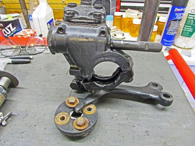
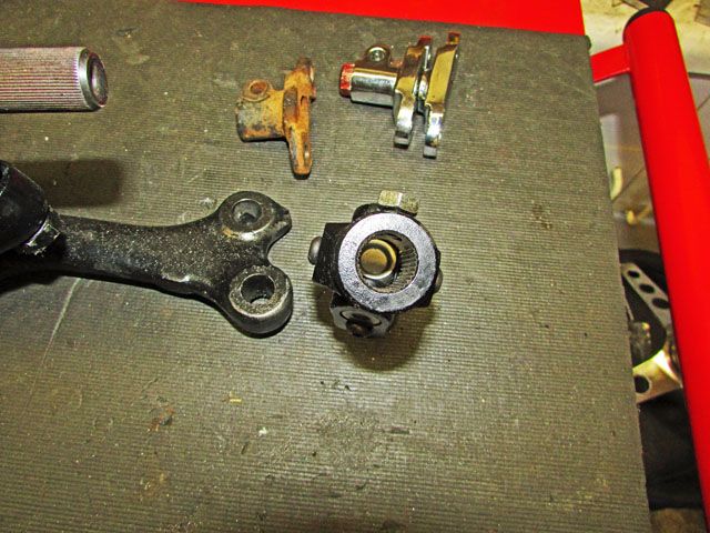
This is the steering box I am using. It seems to be in good shape and the worm and selectors seem to be nice and tight. By the part number it is a type 3 steering box and yes I do have the matching Pittman Arm. After a lot of counting… by several different people the spline count seems to be 48 splines.

The first suggestion I was given was to use the stock VW rag join but because of the angle tightness of the situation the stock rag joint would not fit the situation. Rough dimensions that I am dealing with here are: From the beam to the fire wall is ~10” to 12”. The rough dimension from the inside of the fire wall to the bottom of the dash is~25”. The bottom of the dash to the floor is 22”. When sitting in the driver’s seat the distance from the dash to the front of the seat back ranges from 28 ½” to 34 ½”.
Based on the two people sitting at the farthest distance and very close to the foremost seating position holding on to the steering wheel at a comfortable location ranges from 3” to 3 ½” and the height of the steering shaft at the dash is 20 ½” to 22 ½”.

With the steering box in its normal position mounted on the beam the angle of the worm gear shaft is very steep and the rag joint would not allow the steep angle. It was suggested that the steering box be rotated some as on the sand the slippage is enough not to bother things too much but I do have some pavement to transverse so that suggestion was nixed pretty quick.

Image

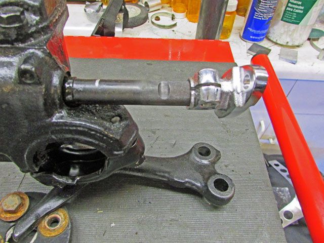
This is the chrome aftermarket version of the rag joint connector. It and the piece that goes into the steering column cost ~$20. Their spline count is again 48 splines. The part shown in the picture shows about where the fitting sits after some pushing and shoving; it should go clear to the end of the mount. The splines stop close to where the end of the split is (this is probably important).

Image

This is the same fitting as the chrome one but came off one of the beams that Daron gave me. I do not feel as bad farting around with it as I would with the $$$ units.

Image

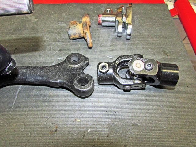
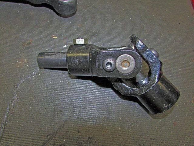
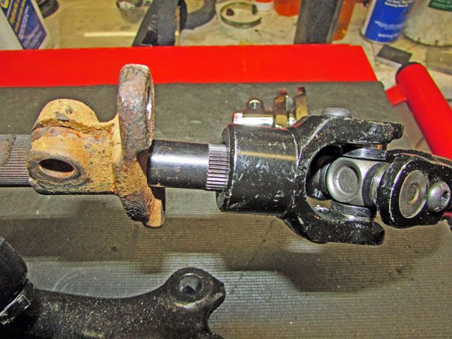
This is the second option we worked with. It is a universal that is splined on one end and a slip-in fit on the other end which is where the steering shaft attaches. It was available in 36 or 48 splines but the 48 spline is for a ¾” dia splined input (it is also available in smooth in some universals. The 36 spline unit does not match up to not only the spline count of the steering box but the shaft dia I will be using also.

Shaft diameter was based on the quick disconnect I got many years ago. Not knowing the difference back then I got the 7/8” rather than the ¾” or the 5/8” so everything must match up with the 7/8” steering coupler.

Image

This shows the input splined area of the universal.

Image

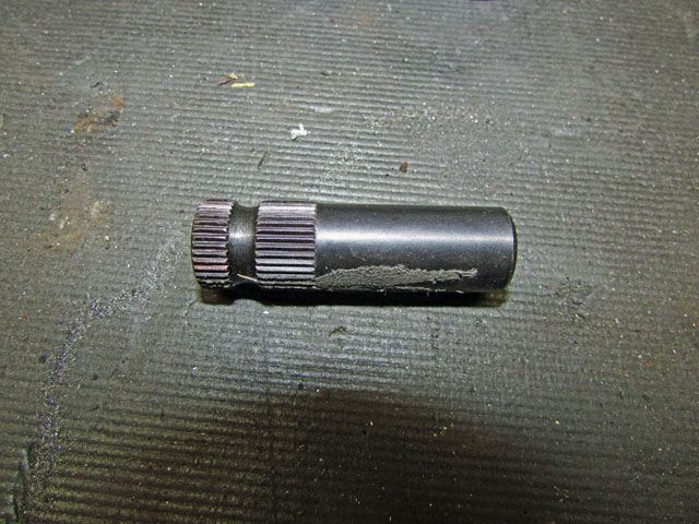
This is the adapter you can order that fits in the universal. This is the 2” version and I think there was a 6” or 8” version of it with the longer version not usable again because of the steering angle. Notice the grove around the splined area for the universal’s lock setup to slip into.

Image

This is how it fits in the universal; it is a nice smooth fit.

Image

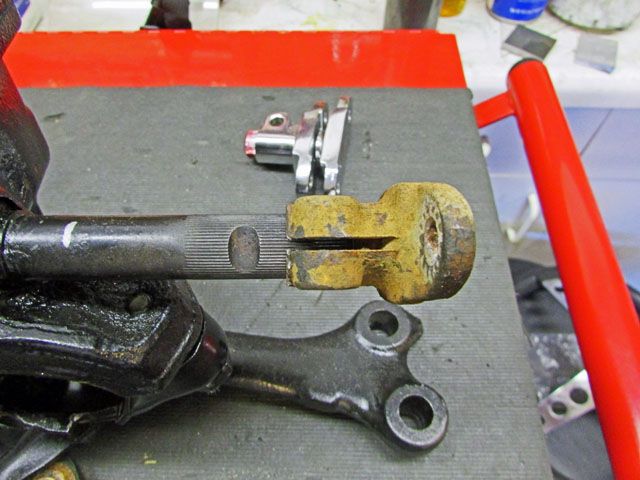
Now we are getting down to the tight jaw area for me. The suggested solution here was to machined off the splined area, bevel both the worm gear shaft and the adapter shaft then have the shafts welded together. One problem would be with the heat and the second problem(s) would be that there would need to be a sleeve over the joint and the worm shaft dia was slightly larger than the adapter shaft. The machinist would not do it for me mostly for liability reasons.

He did suggest that a machinist in the next town north of me spline the shaft but it would be expensive assuming they would even do it.

Image

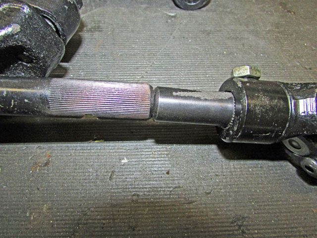
This is the last suggestion and while I don’t like it, it isn’t really much, if any, worse than VW used.

The rag joint end would have the adapter welded into the flanged end of the adapter (the flanges would be removed) after a thin adapter was made as the shaft diameter of the adapter and the mount are slightly different.

The splines of the worm gear shaft would have to be shortened so the hole in the adapter for the locking bolt would fit into the relief on the worm gear shaft. Doable… yes as long as I don’t do the welding. I think it need to be TIG welded to get penetration, not to get the heat up and to capture the adapter all in the one weld. I am also not sure that at least one plug weld would need to be done.

Lee
User avatar
ajdenette
Posts: 717
Joined: Wed Jan 20, 2010 1:18 pm

Re: Ol'fogasaurus black buggy

Post by ajdenette »

Lee I was thinking along the same lines after looking at the photos of the parts and thought along the same lines of adapting the vw fitting to the universal.
Alex

|_________oo_oo
/ /__/____[_____\
I I======[]IIIIIII[]
()_)-----()_)----)_)
Ol'fogasaurus
Posts: 17756
Joined: Mon Nov 13, 2006 10:17 pm

Re: Ol'fogasaurus black buggy

Post by Ol'fogasaurus »

Not my favorite way but if VWs are using them and the rag joint brackets have been use off-road for years it is worth a try.

Lee
User avatar
Marc
Moderator
Posts: 23741
Joined: Thu May 23, 2002 12:01 am

Re: Ol'fogasaurus black buggy

Post by Marc »

Back when I built a mini-super for my son I needed an odd-ball U-joint to connect the Mustang II R&P - found it at Flaming River. They've got many types available, and the U-joints can be ordered with different halves for adapting mismatched components.
You can also ignore the splines altogether and grind flats on the shaft to accept a "double-D" coupler.
http://www.flamingriver.com/index.php/p ... 8/FR1939-4
Ol'fogasaurus
Posts: 17756
Joined: Mon Nov 13, 2006 10:17 pm

Re: Ol'fogasaurus black buggy

Post by Ol'fogasaurus »

I/we ("we" being Doug at Autovice/Bow Wow and i) looked at several different U-joints before and after i got what I have. What you posted is one of many options I/we considered when I was under the impression the spine count of the VW steering box was 36 splines, not the 48 it turned out to be. The other problem was that I already had the steering wheel connector I got at Bug Germinator (North Bend OR) many years ago.

The 7/8" dia is overkill but I will have to live with it and I am more than a little bit comfortable with the hefty size. :roll: As I remember the universal's 36 or 48 splines counts are to match the splines counts that are common to r/p steering boxes. Shaft sizes (splines or smooth) are 5/8, 3/4 or 7\8 which seem to be pretty standard as far as I can tell. The steering shaft supports and quick release steering wheel mounts seem to match these three shaft sizes.

I spent a couple of weeks on looking around on this and Doug got more than a couple of stony looks from me as I constipated (contemplated) on his suggestions. I'm one of those who has to spend time considering the pros and cons on certain things especially if it sounds dicey or dangerous.
Ol'fogasaurus
Posts: 17756
Joined: Mon Nov 13, 2006 10:17 pm

Re: Ol'fogasaurus black buggy

Post by Ol'fogasaurus »

Just in case anyone was interested:

I got the BJ’s pressed out of the two lower arms that I wasn’t able to get pressed out a couple of days ago. I ended up having to trim away the flange created by the ball-joint stud when there must have been a hard suspension hit. Once I got it out of the way the BJ came out but still with a bang and everything flying about.

The other trailing arm, once I got looking at the BJ also had a flange on it wasn’t flaired and bent out as bad as the other one. After some work arounds including using a length of thick wall square tube I was able to get the BJ and trailing arm to part company… again with a bang, flying parts and a disappearing BJ. I still haven’t found it.

Image

This is one of the two spindles that I got with the beams. I think it is the worse of the two but time will tell. I decided to see just how bad it was so into the blast cabinet. I am using glass beads instead of sand so the metal doesn’t get compacted and brittle.

Image

This is a session of work in the blast cabinet. I didn’t see how long I took but it probably was about 15 minutes. It could be worked on some more assuming that it is usable.

Image

Image

Two different close up on the spindle’s spud showing some damage. I will have to have a person that knows what they are doing but in my opinion it might be marginal. I am not sure were the outside bearing rides on this but is it pretty close to here. The inside bearing are isn’t too bad as is the area where the seal rides but an expert should be able to give me a good idea if it is OK for off-road and/or street.

Image

I think this is one of the other spindles for comparison. I did notice, since I have things spread out as I go through things that there is another spindle with the bearing still in place but it should take just a few seconds to press it off.

Lee
Ol'fogasaurus
Posts: 17756
Joined: Mon Nov 13, 2006 10:17 pm

Re: Ol'fogasaurus black buggy

Post by Ol'fogasaurus »

I went to my local VW shop to see if the one spindle was going to be usable. I had bead blasted the mating spindle but it looks to be OK. While there my shifter came in. It wasn't supposed to be here until the end of the month but now I can check it out to see what the straight up handle does to the turning brake setup I have.

Image

This is the new shifter loosely in place. With the straight up handle it does allow for the turning brakes handles to be set a bit farther forward.

Image

This shows the two handles sitting at different angles. The handle laying down a bit is about as far forward as I can adjust it based on where I am sitting. The other handle is still in the straight up position that is came in. The seat is going to have to be moved a bit towards the center to allow for the seat to get full slide forward for the shorter people in our group.

Image

This is the fly in the ointment. It shows just how much the handles might have to be lowered in order to get to the shifter. My arms are going between the two handles so I have a good idea of what I am going to have to do. The top of the shifter is 12” up from the mount and, other than the bus sifter while will not work in a bug as the ball that goes into the shift rod sits too deep into the tunnel.

I like the Drag fast unit for its not too short of throw which allows better timing when double clutching into first when you reach the top, or get stuck near the top of a dune.

Image

Another fly in the ointment. The driver’s seat needs to be slid to the center of the buggy more as the taper in the body and pan makes the wide seat hit the side before full forward adjustment; a goof on my part. I will have to slot the seat mount bracket some for the fit. I thought I had that figured out but since I used the two spaces I used to help straighten the seat mount I got too close to the side.

Another problem is the brake line connectors will be too far over on the passenger side which makes them susceptible to getting damn-aged. It is looking like the turning brake cylinders are going to have to be sitting remote as Ryan’s setup is. I thought I had that problem solved.

I almost forgot: the spindle in the last post is going to be OK to be used.

Lee
Ol'fogasaurus
Posts: 17756
Joined: Mon Nov 13, 2006 10:17 pm

Re: Ol'fogasaurus black buggy

Post by Ol'fogasaurus »

Image

I have been working on rebuilding a new beam for the buggy but going kind of in the way of a Type III beam way of doing things. I had been given a pair of ball-joint beams so I went after the worse off the two beams to do some experimenting on. I did get a lot of information on it but the beam was just too far rusted out and was getting too involved replacing things so it was recycled a couple of days ago. I will document what I found out in the beam build that I have already given the URL for.

The buggy is now back on the body stands mounted on the dollies so the buggy can be moved around easier allowing me to have more room to work on the new beam. I thought that some of you might be interested in what it would look like from sitting in the driver's seat so I am posting this pix that was taken yesterday. Sorry it is so busy but at least you can get an idea of what it would look like sitting in it. Sorry about the tight confines of the garage and what the camera sees but this is the best I can do right now.

I did have an interesting thing happen which I discovered when checking out what I am going to have to do to move the seat in towards the center of the pan (seat to body clearance in the forward seating position). If you go back in the string and look at the underside of the pan you will remember that I had put a square tube down the body mount tunnel to stiffen the pan sides up as, without them or the body lift, the sides of the pan flex quite a bit with no steel body with a roof to support them. As it sits now, the body and the 3" body lift I built are sitting on the pan but the whole assembly is not bolted together.

With my getting in and out of the buggy to fit the seats (~210#s) and with my other two people getting in and out (+/- my weight) that were there to help me to fit min and max seat travel the thick walled 1" square tubing took a slight set to it. It now has about an 1/8th inch or less gap from the body lift but not a worry as it will pull back in shape after everything is done and the long body bolts are installed. Right now there is one body bolt in place, in the seat area, to hold things up a bit better.

Lee
Ol'fogasaurus
Posts: 17756
Joined: Mon Nov 13, 2006 10:17 pm

Re: Ol'fogasaurus black buggy

Post by Ol'fogasaurus »

I did some work on the mounting of the driver's side seat today. Even with a fair amount of rethinking and hand work of the seat mount holes the seat still sits too far outboard. Slotting the mount plate and eliminating the two other mounting pieces that came with the floor mount kit got me way from the side of the body at almost the most forward position of the slide. If someone needs the seat clear forward it still rubs which would ruin the side of the upholstery by rubbing the side of the body. The trouble is that the adjustment is still not enough to make the critical difference.

I am going to make a new, thicker seat base mount that connects to the seat's floor mount. It will offset towards the tunnel more than the one I already made can be. I don't want to slot the pan as it's material is really too thin to make a slot work safely unless I add some kind of a doubler(s)... which is still an option. I think I can get the brake lines to sit high enough on the tunnel to pass by the flanged seat mount to eliminate possible abrading on the seat mount.

Lee

What seems easy is always so.
Ol'fogasaurus
Posts: 17756
Joined: Mon Nov 13, 2006 10:17 pm

Re: Ol'fogasaurus black buggy

Post by Ol'fogasaurus »

If you ever wondered what my buggy could have looked like on the street:


http://portland.craigslist.org/mlt/cto/5864639545.html

This is for sale still.
User avatar
dustymojave
Posts: 2312
Joined: Mon Dec 01, 2008 9:08 pm

Re: Ol'fogasaurus black buggy

Post by dustymojave »

Image

Ummm...Do you climb in, swipe your debit card, and it makes motor noises and bumps up and down for a couple minutes? Didn't this used to sit outside the door of K-Mart?

:twisted:

8)
Richard
Lake LA, Mojave Desert, SoCal
Speed Kills! but then...So does OLD AGE!!
Tech Inspection: SCCA / SCORE / HDRA / ARVRA / A.R.T.S. OffRoad Race Tech - MDR, MORE, Glen Helen BajaCup
Retired Fabricator
'58 Baja with 955K Miles and counting
cbeck
Posts: 243
Joined: Tue Oct 20, 2015 5:17 pm

Re: Ol'fogasaurus black buggy

Post by cbeck »

But instead of quarters it needs 100$bills.
Ol'fogasaurus
Posts: 17756
Joined: Mon Nov 13, 2006 10:17 pm

Re: Ol'fogasaurus black buggy

Post by Ol'fogasaurus »

cbeck wrote:But instead of quarters it needs 100$bills.
Aaaaaah....... yeah! I have had one direction right from the start but also a whole swerves along the path. I also have had a bunch of expensive lessons/detours along the way. I hope everyone learned things along the way as I have.
Ol'fogasaurus
Posts: 17756
Joined: Mon Nov 13, 2006 10:17 pm

Re: Ol'fogasaurus black buggy

Post by Ol'fogasaurus »

I got to do some part buying today for the turning brakes on the buggy. If you remember, I am going to use the remote turning brake idea that I've posted here before.

Image

This is the hookup for the stock turning brake handles and the cylinders. As you can see, the threads allow you to tilt the handles forward some.

Image

This is the All-thread stock I bought. I got two lengths of M8 X 1.25 (thread pitch) and is one meter long and Zinc coated for $8.22. I will need to run it through a sleeve to keep the threaded stock from bending/folding as it isn’t really that strong by itself. The square stock shown here is too big inside to work and the proper round stock can’t be had as far as I can tell. I am getting some ¼” tube that should work as I will put jam nuts on the All-thread at each end which will transfer most of the loading to the tube.

Image

This is the coupler that will allow me to connect the All-thread to the turning brake unit. It was $1.39 for the both of them.

Image

This is the stock clevis with the all thread attached. I will have to make a new mount for the handles to fit to and it will have to be made level with where the cylinders will be mounted… about 2’ behind the handles. This is all needed because the seats are so wide they have to be shifted over closer to the tunnel so that at full travel the seat covers won’t wear on the side of the body.

With what I have posted and nuts to work as jam nuts I am into this today $11.05 and that includes $0.99 sales tax.

I almost forgot: I will have to build a strong metal cover for this area. The seats will sit so low that people usually push on the tunnel to help themselves get out of their seat (I am to blame at times also). Quite often it is the turning brake unit or the hydraulic lines that the push on hence the cover for the long rods.

Lee
Post Reply