Basic Off-road Ball-Joint Beam rebuild PT 2 starts on p. 13
-
Leatherneck

- Moderator
- Posts: 17104
- Joined: Sat Jul 01, 2006 6:47 pm
Re: Basic Off-road Ball-Joint Beam rebuild PT 2 starts on p. 13
Keep the updates coming
-
dustymojave
- Posts: 2312
- Joined: Mon Dec 01, 2008 9:08 pm
Re: Basic Off-road Ball-Joint Beam rebuild PT 2 starts on p. 13
BTW...We've been discussing plate towers. The typical thickness of plate used is 1/4", not 1/8".
Towers can very well be made of 1/8" plate, especially if the design is right. The triangular design as I described above would work. I've built them for link pin beams on 1600 race buggies before with good results. Note that link pin towers are quite a bit taller than ball joint, thus more bending leverage applied to them than if the towers were on a ball joint beam.
Towers can very well be made of 1/8" plate, especially if the design is right. The triangular design as I described above would work. I've built them for link pin beams on 1600 race buggies before with good results. Note that link pin towers are quite a bit taller than ball joint, thus more bending leverage applied to them than if the towers were on a ball joint beam.
Richard
Lake LA, Mojave Desert, SoCal
Speed Kills! but then...So does OLD AGE!!
Tech Inspection: SCCA / SCORE / HDRA / ARVRA / A.R.T.S. OffRoad Race Tech - MDR, MORE, Glen Helen BajaCup
Retired Fabricator
'58 Baja with 955K Miles and counting
Lake LA, Mojave Desert, SoCal
Speed Kills! but then...So does OLD AGE!!
Tech Inspection: SCCA / SCORE / HDRA / ARVRA / A.R.T.S. OffRoad Race Tech - MDR, MORE, Glen Helen BajaCup
Retired Fabricator
'58 Baja with 955K Miles and counting
-
Ol'fogasaurus
- Posts: 17761
- Joined: Mon Nov 13, 2006 10:17 pm
Re: Basic Off-road Ball-Joint Beam rebuild PT 2 starts on p. 13
I guess I did not understand that you were talking about 1/4" plate, I was under the impression we were talking half that thickness. A whole new game !
I have played with K&L only once so I would have to look at the pixs' I took to see some things I an concerned about. Never-the-less I still would be concerned about the weight that would be added with the thickness of the 1/4" towers. Remember, I am playing in PNW sand (sand thrown on shore by the ocean) which, I understand, is a bit different than sand in other places.
It would be easier for me to change frame heads and go with the K&L beam than to play with the limitations of the BJ beam but then, even with the body lift, I would probably have to cut the body to accept the taller towers I would want to use which also means that the IRS would have to be modified to keep within the 60% - 90% travel, front to rear travel range.
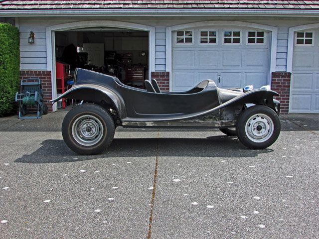
If myblue buggy wasn't considered so rare I might consider doing thao but then the short wheel base comes into play. The black buggy... no I would not even consider it!
Good conversation for this subject as my build is/may not be the same needs as others who build a BJ beam might be so different ideas could be very relevant. Thanks dusty !
Lee
I have played with K&L only once so I would have to look at the pixs' I took to see some things I an concerned about. Never-the-less I still would be concerned about the weight that would be added with the thickness of the 1/4" towers. Remember, I am playing in PNW sand (sand thrown on shore by the ocean) which, I understand, is a bit different than sand in other places.
It would be easier for me to change frame heads and go with the K&L beam than to play with the limitations of the BJ beam but then, even with the body lift, I would probably have to cut the body to accept the taller towers I would want to use which also means that the IRS would have to be modified to keep within the 60% - 90% travel, front to rear travel range.
If myblue buggy wasn't considered so rare I might consider doing thao but then the short wheel base comes into play. The black buggy... no I would not even consider it!
Good conversation for this subject as my build is/may not be the same needs as others who build a BJ beam might be so different ideas could be very relevant. Thanks dusty !
Lee
-
Ol'fogasaurus
- Posts: 17761
- Joined: Mon Nov 13, 2006 10:17 pm
Re: Basic Off-road Ball-Joint Beam rebuild PT 2 starts on p. 13
As usual, Photobucket is being a butt  so I can't post the pictures I have but the trailing arms on a King and Link are quite a bit different than BJ.
On the K&L the trailing arm bends outboard just before (a bit before halfway down the trailing arm) the boss for the shock mount so the shock is mounted quite a bit forward and inboard than the BJ shock mount.
The shock mount for a BJ trailing arm is mounted very close to the inboard side of the lower ball-joint mounting location itself and it short making it much farther outboard than the K&L shock mount is.
If Photobucket stops being an A$$ H??? I will try to post some pictures tomorrow but it might be in several edits as that is the way PB seems to be working right now; get one or two pictures (if you are lucky and it takes several tries just to get the first one) then one or two more usually over many more tries, that is when PB isn't locking up. My refresh button is wearing the print on top of the key
 with all the refreshing I have to do.
Lee

On the K&L the trailing arm bends outboard just before (a bit before halfway down the trailing arm) the boss for the shock mount so the shock is mounted quite a bit forward and inboard than the BJ shock mount.

The shock mount for a BJ trailing arm is mounted very close to the inboard side of the lower ball-joint mounting location itself and it short making it much farther outboard than the K&L shock mount is.
If Photobucket stops being an A$$ H??? I will try to post some pictures tomorrow but it might be in several edits as that is the way PB seems to be working right now; get one or two pictures (if you are lucky and it takes several tries just to get the first one) then one or two more usually over many more tries, that is when PB isn't locking up. My refresh button is wearing the print on top of the key
Lee
-
dustymojave
- Posts: 2312
- Joined: Mon Dec 01, 2008 9:08 pm
Re: Basic Off-road Ball-Joint Beam rebuild PT 2 starts on p. 13
Photobucket seems quite capable of being obnoxious.
I think you're picturing plate shock towers straight vertical just like link pin towers. I was picturing them curved outboard at the top, rather like the stock towers. If the shocks were eye/eye, rather than pin type, the upper mount boss would need to be a bit more outboard than for a link pin beam.
But all of this aside, you COULD use a conversion beam that fits in a ball joint frame head and uses link pin arms and spindles with link pin towers. It would cost around the same as a replacement frame head to convert that.
Richard
Lake LA, Mojave Desert, SoCal
Speed Kills! but then...So does OLD AGE!!
Tech Inspection: SCCA / SCORE / HDRA / ARVRA / A.R.T.S. OffRoad Race Tech - MDR, MORE, Glen Helen BajaCup
Retired Fabricator
'58 Baja with 955K Miles and counting
Lake LA, Mojave Desert, SoCal
Speed Kills! but then...So does OLD AGE!!
Tech Inspection: SCCA / SCORE / HDRA / ARVRA / A.R.T.S. OffRoad Race Tech - MDR, MORE, Glen Helen BajaCup
Retired Fabricator
'58 Baja with 955K Miles and counting
-
Ol'fogasaurus
- Posts: 17761
- Joined: Mon Nov 13, 2006 10:17 pm
Re: Basic Off-road Ball-Joint Beam rebuild PT 2 starts on p. 13
I have a K&L frame head, had it for many years so that could be done, just not on the black buggy. I had forgot about the conversion beam but it still has the tower problem.
The pattern frame I was making was about what you are talking about but I never considered 1/4' material;1/8" flat stock is what I was thinking at the time. I really never thought about going past the first bend of the square tube as I was just showing options as your, Marc's and others plus my opinions have talked about. The one thing that still concerns me is the potential racking the post on a hard hit even with the ×/4" bent flat stock. One of the advantages if the four surfaces, backed up by doublers, and the spread of the stock sheet metal tower.
With what Marc told me about the BJ splines I think I am going to try that before I get too creative right. The other thing is not ruled out assuming that Marc's idea doesn't plus it is cheaper for now. My wife is pressing met sell the black buggy again.
I think that BJ beams have been largely ignored and maybe this discussion will drive am additional thinking on them.
-
Ol'fogasaurus
- Posts: 17761
- Joined: Mon Nov 13, 2006 10:17 pm
Re: Basic Off-road Ball-Joint Beam rebuild PT 2 starts on p. 13
Guy’s, this has been a great discussion and I would like to continue it a bit farther if you don’t mind.
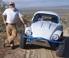
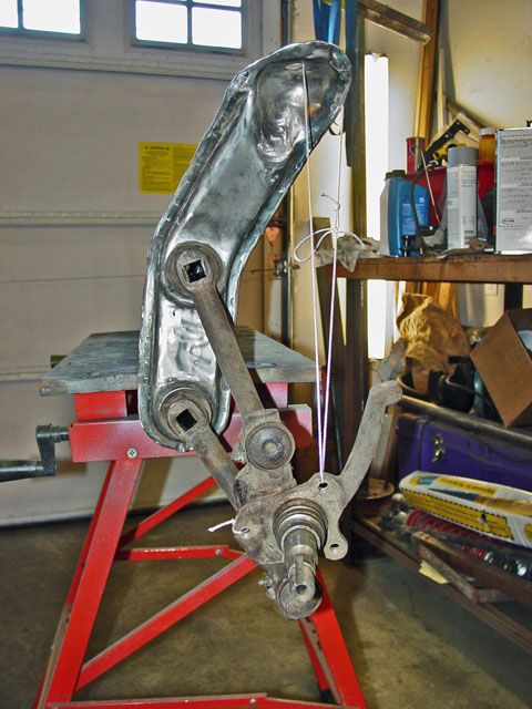
As you can see, I am limited by travel both in the rear and up front. The body/suspension has not settled in this pictures but it shows that I am pushing the limit of suspension travel so going longer travel is not really an option in my current plans, at least on this buggy.
Just too (spell check says this is the proper spelling and use in this case of the word to/too/two) muddy the discussion.
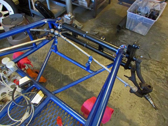
On the K&L beam that will fit into a BJ frame head I have yet to see one; I’ve only heard talk about them so it would be interesting to see pictures. A while back I put the K&L arms and spindle assembly I had and put them into a BJ beam then took pictures of what the spindle did during full travel… just to see what it did so…
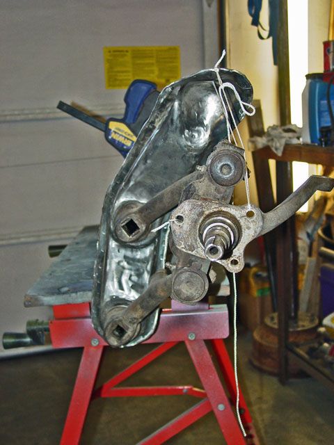
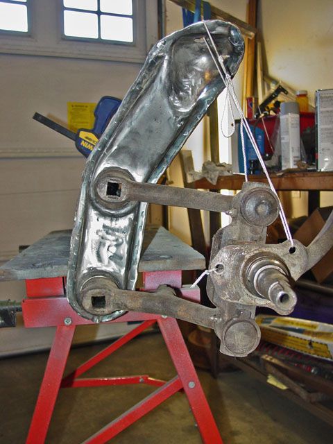
The kingpin angle did what one might call a sine wave (for lack of a better term) like Watts linkage does, but I was told that the travel would be limit by the stops which I was sure of. My curiosity was what the king pin angle did do with the different pivot points between the distance between tubes change between the L&L beam and the BJ beam. Also note the shock boss on the K&L lower trailing arm and its relationship to the shock tower on the BJ beam. I just noticed the picture showed that fairly well.
The other thing of interest is shocks. With the shock mount to close to the pivot end of the trailing arm, note that the spindle arm’s shock travel from full hang to full compression is going to be shorter than the BJ’s shock stud which is very close to the spindle on the trailing arm. When going through shock charts to find the right length of shock travel (~1/2” above and ½” below full compression and full hang) the proper distances were hard to find but while I am sure it could be done but the bigger problem was the lower eye’s diameter to match the shock stud on a VW.
Again, a great discussion, please keep it up as by the view count others are interested I think.
Lee

As you can see, I am limited by travel both in the rear and up front. The body/suspension has not settled in this pictures but it shows that I am pushing the limit of suspension travel so going longer travel is not really an option in my current plans, at least on this buggy.
Just too (spell check says this is the proper spelling and use in this case of the word to/too/two) muddy the discussion.
On the K&L beam that will fit into a BJ frame head I have yet to see one; I’ve only heard talk about them so it would be interesting to see pictures. A while back I put the K&L arms and spindle assembly I had and put them into a BJ beam then took pictures of what the spindle did during full travel… just to see what it did so…


The kingpin angle did what one might call a sine wave (for lack of a better term) like Watts linkage does, but I was told that the travel would be limit by the stops which I was sure of. My curiosity was what the king pin angle did do with the different pivot points between the distance between tubes change between the L&L beam and the BJ beam. Also note the shock boss on the K&L lower trailing arm and its relationship to the shock tower on the BJ beam. I just noticed the picture showed that fairly well.
The other thing of interest is shocks. With the shock mount to close to the pivot end of the trailing arm, note that the spindle arm’s shock travel from full hang to full compression is going to be shorter than the BJ’s shock stud which is very close to the spindle on the trailing arm. When going through shock charts to find the right length of shock travel (~1/2” above and ½” below full compression and full hang) the proper distances were hard to find but while I am sure it could be done but the bigger problem was the lower eye’s diameter to match the shock stud on a VW.
Again, a great discussion, please keep it up as by the view count others are interested I think.
Lee
-
ninelives17
- Posts: 105
- Joined: Tue Aug 27, 2013 11:27 am
-
Ol'fogasaurus
- Posts: 17761
- Joined: Mon Nov 13, 2006 10:17 pm
Re: Basic Off-road Ball-Joint Beam rebuild PT 2 starts on p. 13
Thank you sir, great post!ninelives17 wrote:http://www.bugzyla.com/new/parts.php
This gives more information on options available to BJ beam owners. A lot of older and I think some new rail kits come with the front clamps positioned for BJ beams. Trying to re-bend the frame down to K&L sizes which screws up the beam's geometry as the beam is positioned very close to vertical rather than the top tube tilted backed something like 6-degrees to the rear.
Lee
-
dustymojave
- Posts: 2312
- Joined: Mon Dec 01, 2008 9:08 pm
Re: Basic Off-road Ball-Joint Beam rebuild PT 2 starts on p. 13

In the case of the car we're talking about, the shock towers as shown would probably not clear the fenders of the body. Some other tower shape would have to be invented. Still not an issue for an engineering mind.

The 2nd pic is of the shock tower plate forms he offers. One of those patterns just might serve for making a ball joint tower, if bent in the appropriate locations and reinforced. Those tower plates are made of 1/4" thick plate.
If one needed to move the lower shock mount to near the lower link pin, there are chromoly link pins available with an extension for the shock to mount right to the link pin.
Your pictures of cycling the mock up of the link pin spindles and arms in a ball joint beam show that the extremes chosen are beyond the capabilities of the setup to deal with. The stops would have to be set so they would not allow that much travel.
Richard
Lake LA, Mojave Desert, SoCal
Speed Kills! but then...So does OLD AGE!!
Tech Inspection: SCCA / SCORE / HDRA / ARVRA / A.R.T.S. OffRoad Race Tech - MDR, MORE, Glen Helen BajaCup
Retired Fabricator
'58 Baja with 955K Miles and counting
Lake LA, Mojave Desert, SoCal
Speed Kills! but then...So does OLD AGE!!
Tech Inspection: SCCA / SCORE / HDRA / ARVRA / A.R.T.S. OffRoad Race Tech - MDR, MORE, Glen Helen BajaCup
Retired Fabricator
'58 Baja with 955K Miles and counting
-
Ol'fogasaurus
- Posts: 17761
- Joined: Mon Nov 13, 2006 10:17 pm
Re: Basic Off-road Ball-Joint Beam rebuild PT 2 starts on p. 13
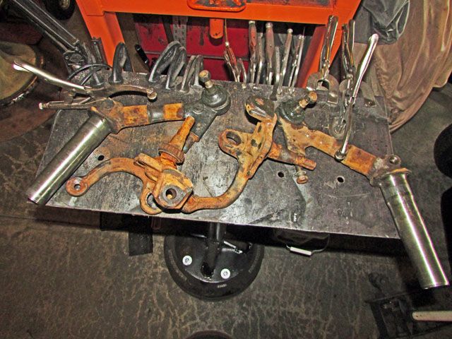
In taking the pictures that I posted all I was curious about was what's when K&L trailing arms did when they were put into a BJ beam, with the wider tube spread, and to see what happened when the suspension moved to the max travel the K&L parts would allow just like I would do with BJ parts when figuring out the suspension limits for the hook and post suspension stops.
I still don't think that hook and posts stop setup would work as well in a single wall (1/4"" thick) mount as it would on a stock VW two piece welded together tower w/doublers added.
I haven't played it out and don't plan to as I don't have the ability do do the math to verify it. If I was planning to head in ghost direction that would be a different thing. When I retired 16 years ago tomorrow I said I would not do or buy CAD even though I taught it. Too expensive to get a program that would do what I wanted it to do. I do think there might be some room for math to be involved in this case because of the angles that may be involved. Remember, I am not an engineer but a tech with 25 of my almost 34 years in the board so I have and seen a lot.
Thanks for the input as it is important at least to me Dusty.
Lee
-
bajaherbie

- Posts: 9959
- Joined: Sat Jul 15, 2006 7:07 pm
Re: Basic Off-road Ball-Joint Beam rebuild PT 2 starts on p. 13
Are you done yet?
Sent from my SM-G920R4 using Tapatalk
Sent from my SM-G920R4 using Tapatalk
Of all the paths you take in life, make sure a few of them are dirt.
-
Ol'fogasaurus
- Posts: 17761
- Joined: Mon Nov 13, 2006 10:17 pm
Re: Basic Off-road Ball-Joint Beam rebuild PT 2 starts on p. 13
If that is what you guys want I am.bajaherbie wrote:Are you done yet?
Sent from my SM-G920R4 using Tapatalk
Lee
-
dustymojave
- Posts: 2312
- Joined: Mon Dec 01, 2008 9:08 pm
Re: Basic Off-road Ball-Joint Beam rebuild PT 2 starts on p. 13
Hoib seems a little annoyed tonite. Too many Tricksters and not enough treats? 

I'm far from done here. So let's keep going without him Lee.
Don't worry about not being an engineer. The world's full of those that the old saw applies to..."Yistaday I coodn't spell it, today I is one!"
I'm not new to this stuff either Lee. I worked with CAD for many years. I don't have a degree in Engineering either, but I DO have a PhD from the School of Hard Knocks. And I've done the engineering on a great many projects while another guy with the degree took the credit (and the pay) for the work I did.
But in my lexicon, "CAD" can stand for "Cardboard Aided Design". No need for math or expensive software or a College Degree. Cardboard, pencil, ruler, push pins will git 'r dunn!...
Richard
Lake LA, Mojave Desert, SoCal
Speed Kills! but then...So does OLD AGE!!
Tech Inspection: SCCA / SCORE / HDRA / ARVRA / A.R.T.S. OffRoad Race Tech - MDR, MORE, Glen Helen BajaCup
Retired Fabricator
'58 Baja with 955K Miles and counting
Lake LA, Mojave Desert, SoCal
Speed Kills! but then...So does OLD AGE!!
Tech Inspection: SCCA / SCORE / HDRA / ARVRA / A.R.T.S. OffRoad Race Tech - MDR, MORE, Glen Helen BajaCup
Retired Fabricator
'58 Baja with 955K Miles and counting
-
Ol'fogasaurus
- Posts: 17761
- Joined: Mon Nov 13, 2006 10:17 pm
Re: Basic Off-road Ball-Joint Beam rebuild PT 2 starts on p. 13
Thanks Dusty, my wife wants the black buggy gone and the building of stuff too but the mental gymnastics keeps my brain active which is good. I just turned another year and at my age the kind of thinking we do keeps me young... I hope.
BJ beams need some good discussion on what can be done with them and this has bloomed into a great discussion about them.
I agree with the card stock for making templates but then it sometimes needs help
Lee
BJ beams need some good discussion on what can be done with them and this has bloomed into a great discussion about them.
I agree with the card stock for making templates but then it sometimes needs help
Lee