Alyce the Baja

Offroad VW based vehicles have problems/insights all their own. Not to mention the knowledge gained in VW durability.
User avatar
smiley
Posts: 237
Joined: Wed Sep 08, 2010 5:01 am

Re: Alyce the Baja

Post by smiley »

TimS wrote:
smiley wrote:Image


Smiley :)
Would you tell us a little more about this heater unit. Is it an A/C, too? Where did you get it? Junkyard, custom? Thanks.
Hi Tim
The unit is actually only A/C, no heat function. I bought it new from a local parts supplier here in Oz. It's just a generic underdash A/C unit. It's a 14850 BTU unit with 4 62mm outlets. Dimensions are 140mm high, 393mm wide and 317mm deep. I chose this one specifically because with a few mods it should fit nicely under a bug dash, especially with a body lift. Plan is to plumb one outlet up into the windscreen vents for demist, have two outlet on the front of the dash and then one onto my feet :mrgreen:


Smiley :)
User avatar
bajaherbie
Posts: 9959
Joined: Sat Jul 15, 2006 7:07 pm

Re: Alyce the Baja

Post by bajaherbie »

i'm with ol' fog, i got tired just looking at the photos!


that old guy does dang good work, he is so busy he would forget to flick his ashes!
Of all the paths you take in life, make sure a few of them are dirt.
User avatar
TimS
Posts: 5723
Joined: Fri Apr 23, 2010 10:11 pm

Re: Alyce the Baja

Post by TimS »

Thanks for the info on the A/C. I look forward to seeing how you install it.
Don’t ever yield your gift of dream; Your knack for gumption, too. For “It’s the crazy ones that have all the fun," if dreamers yearn to do.
User avatar
smiley
Posts: 237
Joined: Wed Sep 08, 2010 5:01 am

Re: Alyce the Baja

Post by smiley »

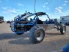
I cut my old battery stops and hold downs off the pan. The battery will be getting moved over slightly to make room for some more stuff. Now that I have the lift kit fitting on the pan I can make sure my extras will actually fit!


Image


First up on the drivers side I'm adding a 600W inverter. It has 2x 240V power points and one USB. Should handle all my needs when camping or travelling. It will be mounted roughly as pictured and poke through the under backseat kick panel. I'm also going to have enough room here to fit my dual battery controller.


Image


Next on the other side I will be running a second battery the same as the first to cover my fridge duties. And I also have as ARB air compressor which will be plumbed in the run the locker and also for reinflating tyres after they are let down. Could probably use it to give the car a blow out too maybe.


Image


After this I pulled one of the seats and bases down off the shelf so I could get some measurements and order some new seat belts. Had to space it up the extra to allow for the added height of the lift kit.
I will be making new seat mounts that mount from the tunnel to the lift kit, giving more room underneath for storage.


Image


Image


About the perfect length.


Image


After this I got the pan down off the rolling bench and leveled it up ready to weld the new framehead on.


Image


Getting everything in position.


Image


Image


Then it was off with the lift kit and measure measure measure.


Image


Image


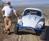
I went and bought an angle finder and used it to measure the castor of the beam. But then I soon realised that this would be wrong due to the uneven spacing of my beam tubes and link pins. So I measured the angle on the spindle itself and am happy to report that with the floorpan level I have about 3° with the top trailing arm level and it gradually increases with more droop. This is due to the uneven spacing. The angle is about 7° between there and halfway to full droop, and around 15° at full droop. This is with no stops in place, I don't think it will be drooped down this far once it's finished.
So all in all I am very happy with the castor.


Image


But then I run into an issue. While measuring the framehead and getting ready to tack it on it seems that the beam is not square there is about 20mm difference at the ends of the beam when I measure back to the rear torsion housing. Turns out that the issue is the beam bolts on one side have cracked and are pulling through from the framehead. When you bolt them up tight they are causing a slight hump where the beam sits in. This is enough to cause a difference of 20mm at the beam ends.

Not sure if you can tell in these pictures but this is the offending side.


Image


Image


Couldn't quite see the cracks under the crud.


Image


Much better.


Image


Image


So I rewelded both sides.


Image


And just to be sure I added a bit of angle to the back to. I never really liked the idea of having those open holes there to let crud in anyway.

Just hit this a little to flatten it so it matches the frame a little better.


Image


Image


And all done!


Image


Now we could get back to the main event!
I got it all back sitting in place again. Took another million measurements then tacked it. Had to tweak it a tiny bit to get the sides even, was out about 2mm. After that I added some more tacks. Then welded it on.


Image


Image


Sat the lift back in place. Starting to look like a whole floorpan again!


Image


I sat the gearbox in place once more and did a little more working out and measuring.


Image


Next port of call with be getting on with the rack setup and dialing in no bumpsteer. Thanks for reading.


Smiley :)
User avatar
Devastator
Posts: 3493
Joined: Tue Nov 06, 2007 6:51 am

Re: Alyce the Baja

Post by Devastator »

What thickness metal did you use on the body repairs?
Devastator's Build Thread

Sandrail

2.4 liter, supercharged Chevy Ecotec

"If everything seems under control, you're just not
going fast enough."
Mario Andretti
User avatar
smiley
Posts: 237
Joined: Wed Sep 08, 2010 5:01 am

Re: Alyce the Baja

Post by smiley »

Devastator wrote:What thickness metal did you use on the body repairs?
Most of the repairs were done with repair panels purchased for the bug. I'd say they are about 0.8mm think?
And anything else I have a sheet of zinc coated that is 1mm from memory.


Smiley :)
User avatar
smiley
Posts: 237
Joined: Wed Sep 08, 2010 5:01 am

Re: Alyce the Baja

Post by smiley »

Small update for today. I spent most of the day at a Camping, Offroading, Caravan etc expo so didn't get much done on the car except some figuring out.

Sat the body on the pan, and I have to say I'm super happy with how it looks. The front shock towers clear with about 30mm to spare which is nice.


Image


Image


Image


And there's heap of room under the rear for the 5 speed.


Image


Image


I put the starter on and measure the clearance to the rear floor. I'm considering recessing the rear tank and dropping it down and it looks like I will have enough room to do it. This will give me more room in the back of the car for camping gear etc and help lower my centre of gravity down a bit too.


Image


Next thing was to set the rack in place and measure what angle I need to lay the shaft back at to meet the steering column. I also dropped the front tank in to check the clearance and there is plenty.
Might use a it more to hold the rack in than magnets though.


Image


That's all for today people. we lifted the body back off and I'm hoping to get stuck into the rack conversion tomorrow.


Smiley :)
User avatar
smiley
Posts: 237
Joined: Wed Sep 08, 2010 5:01 am

Re: Alyce the Baja

Post by smiley »

Got some done on the rack conversion.

First step was to make these little brackets. They match the diameter of the beam and the outside of the rack and are the right size to hold my rack in the right place for no bumpsteer, as far as I have worked out at least.
They got tacked in place on the top beam tube, perpendicular to the front edge of the tubes.


Image


Image


You can see I have a bit of trimming to get the rack in there.


Image


Image


Cut some holes and moved some metal out of the way. Once I got the rack fitting in under there I centred it and set the angle of the input shaft then tacked it into place on the brackets.


Image


Image


Seemed to be all going well until a major setback. Turns out the angle of the racks ends won't allow them to angle back far enough to go in the steering arms for some of the steering angle. It's ok when turned away from the side cause the angle decreases. But turn towards a side and it binds up just past centre. I took a few more measurements and worked out that I had to move that rack back about 10mm to stop the binding, so I made the decision to more it back 15mm just to be sure.


Image


Image


It was at this point I was thinking the bumpsteer would end up being horrible now and that the rack conversion wasn't going to be the success that I had hoped for. I remade the little brackets 15mm longer and tacked everything back into place again. Moving the rack back made half of the holes that I had cut and clearanced into the framehead redundant but that's how it goes I guess.


Image


This time the tie rods fit and the rack ends weren't binding. I could cycle the suspension up and down and full lock on the steering left to right. Then I tried to measure the bumpsteer and came to an unusual conclusion, there wasn't any!


Image


This can't be right I thought to myself. The rack is 15mm from where it is supposed to be, I should have some discernible bumpsteer. I decided that I was trying to measure on too fine a scale on the spindles. So I dug the front discs and bearings out and fitted them up. And then fitted the front wheels. Did a rough wheel alignment and cycled the front suspension up and down and took more measurements.
I ended up with about 2mm of toe variation at the outer edge of the wheel in 12 inches of travel, except right at full droop it goes a bit funny right in the last half inch and gets about 6mm toe in. But I don't foresee this as a problem cause the stops will limit travel before this point.
I couldn't believe it and obviously was very happy with this result!!


Image


Full droop to full bump is around 300mm (12") of travel. It will probably be limited to around 250mm (10") once I set the stops up. Ground clearance will be awesome once again, it will still easily clear a milk crate at ride height. It clears one and a half at full droop!!


Image


Image


Image


I can't wait to take her for a drive and see how she steers!!

Thanks for reading.


Smiley :)
User avatar
smiley
Posts: 237
Joined: Wed Sep 08, 2010 5:01 am

Re: Alyce the Baja

Post by smiley »

I have a bit of a tech query for any Mk I Golf (Rabbit in America?) experts out there.

That rack I am fitting to the Baja is out of a Mk I Golf and I am wondering if there is meant to be anything else holding the rack ends onto the shaft. It's a fine thread and does up tight. Is this all that is done to fit them on or is there a narrow lock nut that goes on the end?


Image


Image


Image


If anyone that has an early Golf knows can you let me know?


Smiley :)
User avatar
TimS
Posts: 5723
Joined: Fri Apr 23, 2010 10:11 pm

Re: Alyce the Baja

Post by TimS »

That is very interesting about your bump steer. I suspected it would be horrible, but I've never seen an end load rack mounted that close to the beam before either. Thanks for the detailed update, sorry can't help you on the rack mounting.
Don’t ever yield your gift of dream; Your knack for gumption, too. For “It’s the crazy ones that have all the fun," if dreamers yearn to do.
User avatar
Devastator
Posts: 3493
Joined: Tue Nov 06, 2007 6:51 am

Re: Alyce the Baja

Post by Devastator »

That's one of the beautiful things about beam front ends. They don't accumulate much bump steer as you move the steering box, (or rack) around. With A-arms, this is definitely not the case.
Devastator's Build Thread

Sandrail

2.4 liter, supercharged Chevy Ecotec

"If everything seems under control, you're just not
going fast enough."
Mario Andretti
User avatar
smiley
Posts: 237
Joined: Wed Sep 08, 2010 5:01 am

Re: Alyce the Baja

Post by smiley »

Look what I picked up this week. I had always planned to bag the back of the car later done the track. But these came up at a great price so I couldn't pas them up. And I figure that it'll be easier to fit and plumb them now anyway with the rest of the build.


Image


Full droop.


Image


Full bump.


Image


Will keep you posted :D


Smiley :)
User avatar
dustymojave
Posts: 2312
Joined: Mon Dec 01, 2008 9:08 pm

Re: Alyce the Baja

Post by dustymojave »

smiley wrote: Look what I picked up this week.

Image
Cool!!! :D

smiley wrote: Full droop.

Image

Full bump.

Image

Smiley :)
NOT good!! :evil:

The bags NEED to sit on top of the outer end of the arm near the stock bump stop. Stock arms, even boxed or tubular reinforced with one of the kits are NOT going to be strong enough to handle the stress of mounting the bags there where you show them without bending the arms. An arm designed for that setup could work, if designed from scratch for it.
Richard
Lake LA, Mojave Desert, SoCal
Speed Kills! but then...So does OLD AGE!!
Tech Inspection: SCCA / SCORE / HDRA / ARVRA / A.R.T.S. OffRoad Race Tech - MDR, MORE, Glen Helen BajaCup
Retired Fabricator
'58 Baja with 955K Miles and counting
Ol'fogasaurus
Posts: 17760
Joined: Mon Nov 13, 2006 10:17 pm

Re: Alyce the Baja

Post by Ol'fogasaurus »

I agree with Dustymojave on this. You are putting a lot of loading on the smaller (in diameter) pivot end of the trailing arm rather than having it sitting out where the load would normally been carried by the torsion setup. The spring plates should keep some of the potential flexing out of the trailing arm but like Dustymojave said, the trailing arms now need to be designed to match this kind of setup.

I know this has been done before but it doesn't mean that it is correct either. I also suspect you are not going to take an gentlemanly ride along the boulevard in your Baja all the time either (in otherwords: "pound it to pieces papa" :wink: ).

Lee
User avatar
smiley
Posts: 237
Joined: Wed Sep 08, 2010 5:01 am

Re: Alyce the Baja

Post by smiley »

I take it you guys have built air bagged Bajas and had the arms bend?

I understand where the ideal location for the bags are. But at this point it just won't be possible to fit them there. Maybe one day if I go bigger arms and longer travel.

The loading on the arms will be very minimal as I am only fitting them to compensate for the weight of loading the car up to go camping. It'll be less than 10psi in each bag which is about 50kg of weight supported there.

I will not be using the bags as a primary spring, nor will I be putting much pressure in them at all.
I have a friend that runs bags in his in pretty much the application that I have described for at least the last 18 months and he hasn't bent anything yet.

I do thank you for your concerns and input though.


Smiley :)
Post Reply