Pete, I agree with doing both... which is what I did. I run in rough territory which is why I did it that way.
The spot welds still allow movement in the formed metal join and can pop lose if the action gets too severe. I did a full seam weld on my buggy just to take any potential weakness out of the game.
Hard acceleration, a lot of torque, hard cornering and bouncing around can cause the cantilevered enine and tranny hanging out the back to move around appropriately to what is being done to them.
Mendola's design, for IRS only, has each brace working against each of the other braces tying everything together... stiffly. The triangle is the tying together of everything.
Rear suspension, engine, and trans. bracing points
-
Ol'fogasaurus
- Posts: 17756
- Joined: Mon Nov 13, 2006 10:17 pm
-
Ol'fogasaurus
- Posts: 17756
- Joined: Mon Nov 13, 2006 10:17 pm
Re: Rear suspension, engine, and trans. bracing points
As long as this subject is being talked about there are a couple of other things that should be mentioned.
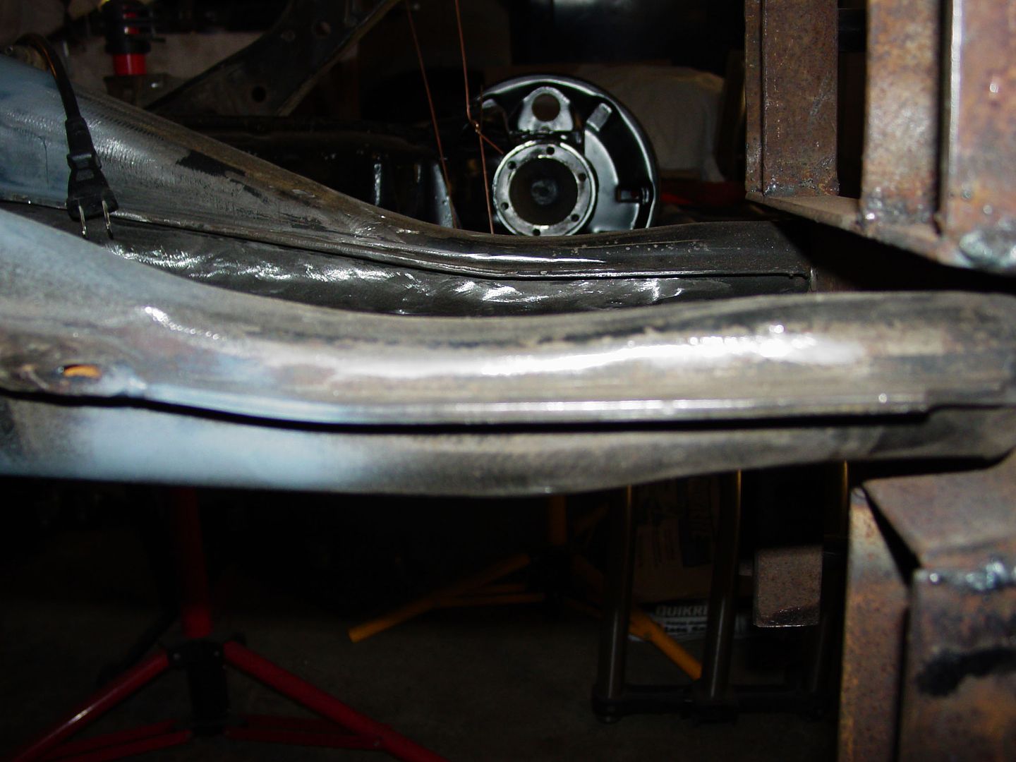
This is the torsion tube connection, under the bottom of the torsion tube, which connects to the rear cross-piece section; e.g., the body bolts to pan in the rear. There are holes for 4 bolts that hook the body to the pan, two on each side.
This hook on the torsion tube welds to the “tin” material of the pan at the outside ends of the rear cross-piece. This “hook” is known for breaking which, when it does only leaves the tunnel connection to the torsion bar to keep the torsion bar from racking side to side. It was recommended to me, by a certified VW mechanic, that additional connections from the pan to the body be added. One on each side is a minimum and two per side is recommended. I am planning on making a simple torque arm from my body lift to the torsion housing and connected by a removable bolt.
The idea of a truss bar is kind of funny as the bar connects the shock mounts together then connects the bar to the ends of the pickle forks which is good but remember, the torsion tube is carrying all the loads and not much of it goes back into the body other than at the hook at the ends of the tube and at the pan’s connection at the tunnel. Even the Mendola’s IRS truss bar, with the extra connection at the trailing arm’s pivot bracket, is still completely located entirely on the torsion tube.
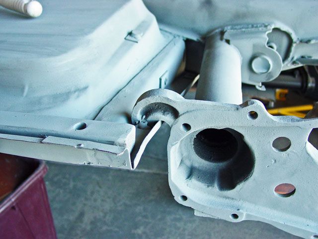
On a IRS pan, this is the area where the CV joint crosses the pickle fork; a weak spot.
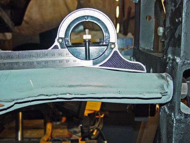
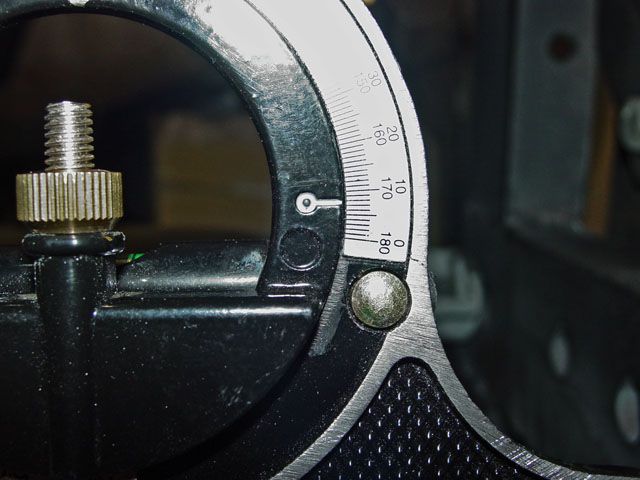
This is the bottom of the pickle fork showing the angle that accommodates the deflection when the engine and transaxle are installed.
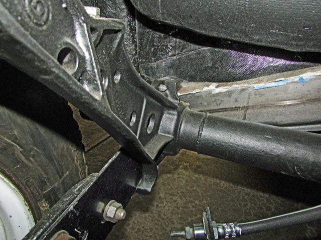
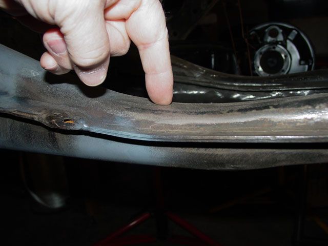
This is a partial picture of another weak spot on the torsion tube… the shock tower. On the sand this area takes a lot of abuse especially with re-valved shocks which is one of the reasons the longer travel shocks (including multiple shocks) are moved from the button hole at the top of the shock tower to the cage.
One fix is to box both sides of the casting but the shock eye is still at risk. I have seen several rails that still run the torsion tube with the shock eye busted off.
All of this is one of the reasons the tube under the torsion tube and pickle fork isn’t the best of fixes… it is still tied directly to the torsion tube and no where else.
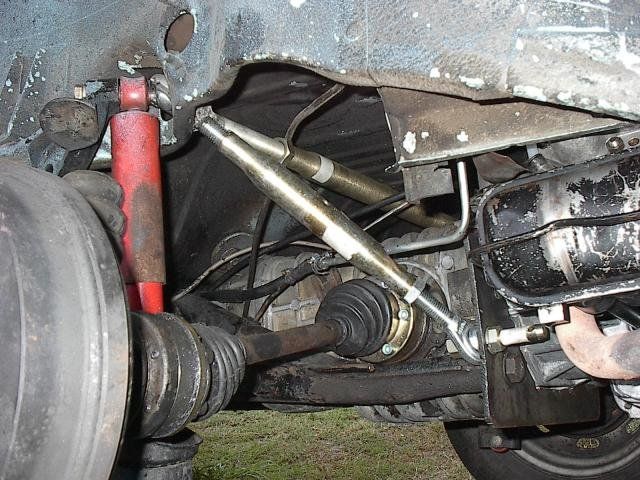
I almost forgot, I think this is FJs version of the truss bar. If it is his I think I remember him saying that he got the parts from Tractor Supply. If it isn't FJs then please speak up to get credit for the design please.

This is the torsion tube connection, under the bottom of the torsion tube, which connects to the rear cross-piece section; e.g., the body bolts to pan in the rear. There are holes for 4 bolts that hook the body to the pan, two on each side.
This hook on the torsion tube welds to the “tin” material of the pan at the outside ends of the rear cross-piece. This “hook” is known for breaking which, when it does only leaves the tunnel connection to the torsion bar to keep the torsion bar from racking side to side. It was recommended to me, by a certified VW mechanic, that additional connections from the pan to the body be added. One on each side is a minimum and two per side is recommended. I am planning on making a simple torque arm from my body lift to the torsion housing and connected by a removable bolt.
The idea of a truss bar is kind of funny as the bar connects the shock mounts together then connects the bar to the ends of the pickle forks which is good but remember, the torsion tube is carrying all the loads and not much of it goes back into the body other than at the hook at the ends of the tube and at the pan’s connection at the tunnel. Even the Mendola’s IRS truss bar, with the extra connection at the trailing arm’s pivot bracket, is still completely located entirely on the torsion tube.


On a IRS pan, this is the area where the CV joint crosses the pickle fork; a weak spot.


This is the bottom of the pickle fork showing the angle that accommodates the deflection when the engine and transaxle are installed.

This is a partial picture of another weak spot on the torsion tube… the shock tower. On the sand this area takes a lot of abuse especially with re-valved shocks which is one of the reasons the longer travel shocks (including multiple shocks) are moved from the button hole at the top of the shock tower to the cage.
One fix is to box both sides of the casting but the shock eye is still at risk. I have seen several rails that still run the torsion tube with the shock eye busted off.
All of this is one of the reasons the tube under the torsion tube and pickle fork isn’t the best of fixes… it is still tied directly to the torsion tube and no where else.

I almost forgot, I think this is FJs version of the truss bar. If it is his I think I remember him saying that he got the parts from Tractor Supply. If it isn't FJs then please speak up to get credit for the design please.
Lee
My opinion is worth slightly less than what you paid for it.
My opinion is worth slightly less than what you paid for it.
-
ChadH

- Posts: 254
- Joined: Wed Mar 30, 2016 4:55 pm
Re: Rear suspension, engine, and trans. bracing points
Good stuff! I think I'm addressing some of this in my build.
I've cut some sheet metal to get access to the torsion tube, right at that welded seam. Right now I have a horizontal tie to the cage. I plan, also, to have a vertical tie straight up to the cage.
I agree a typical truss relies on all the forces being transmitted to the top of the casting. With mine, I have some additional sheet metal plating on the inner fender well, and will make a connection from the cage, inside the car, through this thickened area, and onto the casting (sorry - no pictures yet.)
I think I'll take a look at Tractor Supply for those horn connections. They look like a convenient and tidy way to incorporate the horn-end ties.
With my build, I'm not dealing with stresses of jumps and heavy terrain. I'm just trying to make the chassis 100% rock-solid so only the suspension is doing the work for road stuff, so I shouldn't see super high impact loading.
I've cut some sheet metal to get access to the torsion tube, right at that welded seam. Right now I have a horizontal tie to the cage. I plan, also, to have a vertical tie straight up to the cage.

I agree a typical truss relies on all the forces being transmitted to the top of the casting. With mine, I have some additional sheet metal plating on the inner fender well, and will make a connection from the cage, inside the car, through this thickened area, and onto the casting (sorry - no pictures yet.)
I think I'll take a look at Tractor Supply for those horn connections. They look like a convenient and tidy way to incorporate the horn-end ties.
With my build, I'm not dealing with stresses of jumps and heavy terrain. I'm just trying to make the chassis 100% rock-solid so only the suspension is doing the work for road stuff, so I shouldn't see super high impact loading.
-
Piledriver

- Moderator
- Posts: 22520
- Joined: Sat Feb 16, 2002 12:01 am
Re: Rear suspension, engine, and trans. bracing points
RE: Broken shock mounts...
...If you shock is acting as the bump stop you are doing it wrong, regardless.
Neither the shock or the shock mount will like it long.
Also note a full 5 bar kafer brace supports the shock mount some and makes it double shear.
I used a 1/2" grade 8 through bolt. Works fine on a road car.
The rest of the pictures of the "Tractor Supply" brace with part numbers are//were on Tunas site, which has been mirrored elsewhere, IIRC.
A working link once lived at the top of the type4um, but even the wayback machine appears to have deleted all records. I still have the original pics and may have a mirror of the related webpages/how-to.
Please ignore the crummy welds, I only had an old 110v Einhell MIG at the time.
FWIW the heavier T3s used a different bolt in torsion setup, the shock mounts were all stamped/fabricated sheetmetal and bolted to the body vertically through a big rubber donut. (There is structure above the shock mount)
Duplicating that at least for the shock mounts would help.
Addendum to Newtons first law:
zero vehicles on jackstands, square gets a fresh 090 and 1911, cabby gets a blower.
EZ3.6 Vanagon after that.(mounted, needs everything finished) then Creamsicle.
zero vehicles on jackstands, square gets a fresh 090 and 1911, cabby gets a blower.
EZ3.6 Vanagon after that.(mounted, needs everything finished) then Creamsicle.
-
Jadewombat

- Posts: 1447
- Joined: Sat Jun 22, 2002 12:01 am
Re: Rear suspension, engine, and trans. bracing points
Just thinking out loud, what are your guy's thoughts on:
-As Pete showed, the whole rear torsion area/shock mounts/etc. tied together with those welded tubes--then cradle mount/trans. serves two purposes to the engine, to support the weight of the engine and transfer of power. Sudden throttle-on, throttle-off makes the cradle mount a pivot point and the trans nose cone mount a lot of the job of absorbing the torque and hp to transfer the power to the wheels. My question alludes to adding a mustache bar like on the '68-71 busses, good, bad?? Other options?
-Again, the whole rear torsion area tied to together which extends and ties together the two lower torsion tubes forward into the pan rear seat area (by the rear shift coupler). So, hard concerning and braking into a turn followed by hard gas out of that turn--the majority of the transfer of power and handling would be the job of the tunnel (and the body to a lesser degree since that movement is absorbed by the rubber mounts and body seal) in the middle of the car (front seat area) during those events, correct? Sorry if I'm not explaining this well enough. Additional tubes along the tunnel or heater channels to tie the front (beam or struts) all the way to the back of the car (rear torsion area)? I.e. reduce the flex and make the suspension at all four corners do more of the work.
Last edited by Jadewombat on Fri Feb 03, 2017 1:16 pm, edited 1 time in total.
-
ChadH
- Posts: 254
- Joined: Wed Mar 30, 2016 4:55 pm
Re: Rear suspension, engine, and trans. bracing points
I'm rambling and thinking out loud too (it's Friday.)
I can see how a rear engine support (tied to the case, not just a traction bar supporting the engine weight) would really help with twist along the tunnel axis. Ties to the body work (factory reinforced sheet metal for the bumper), are still cantilevered way out at the rear of the car. How stiff is this bodywork against these torsional loads? It seems like it would help, but is the bodywork really "flexy" back there? It would be tough to bring reinforcement way out back in a stock bodied/stock fendered car.
I can see how a rear engine support (tied to the case, not just a traction bar supporting the engine weight) would really help with twist along the tunnel axis. Ties to the body work (factory reinforced sheet metal for the bumper), are still cantilevered way out at the rear of the car. How stiff is this bodywork against these torsional loads? It seems like it would help, but is the bodywork really "flexy" back there? It would be tough to bring reinforcement way out back in a stock bodied/stock fendered car.
-
Ol'fogasaurus
- Posts: 17756
- Joined: Mon Nov 13, 2006 10:17 pm
Re: Rear suspension, engine, and trans. bracing points
On the broken shock mount caused by the deletion of the stops (for additional travel)... I totally agree. I have seen the cheap helper spring type of shock be a strong reason for the shock eye breaking also because they were used for suspension lift vs. doing the suspension correctly;egg., changing torsion bar preload, replacing the torsion bars with properly rated ones and/or going to re-valved/higher quality shocks
The question of using the body for additional support is double edged sword. It think it depends on where, when and how much I think. What ever you use it too has to be supported correctly.
The question of using the body for additional support is double edged sword. It think it depends on where, when and how much I think. What ever you use it too has to be supported correctly.
-
Jadewombat
- Posts: 1447
- Joined: Sat Jun 22, 2002 12:01 am
Re: Rear suspension, engine, and trans. bracing points
Yeah, I'd love to have some fairly accurate instrumentation set up to measure all of this at the corners and different points on the body (g-meters, shock tabs?). Jacking the car up and measuring things wouldn't have quite the same effect, it's just I've auto-xed FWD and RWD newer cars and older bugs and ghias and the old v-dubs just don't "feel" as stiff somehow and I don't think it's just suspension. Keeping in mind VW never intended this use for their cars either.
In theory, a chassis shouldn't move at all...yet we have things like strut tower brace bars and even several manufacturers have adopted them.
In theory, a chassis shouldn't move at all...yet we have things like strut tower brace bars and even several manufacturers have adopted them.
-
ChadH
- Posts: 254
- Joined: Wed Mar 30, 2016 4:55 pm
Re: Rear suspension, engine, and trans. bracing points
I'm sort of discussing some of this more "theoretically" than maybe what is practical or really needed. For instance, bracing the horns is certainly more important for a 300+hp drag car. I'll have maybe 110hp if I'm lucky. I won't be doing hard launches - our local A-X courses are actually set up to discourage drag starts, with a sharp corner or two immediately off of the start.
As far as stiffening the chassis in regards to improving suspension, and handling; Theoretically, eliminating chassis flex is supposed to improve handling, but I have no personal seat-of-the pants experience with comparing similar cars (stock-vs-heavily braced). Without personal knowledge, I'm trying to gauge what provides real benefits versus over-the-top pointless mods.
As far as stiffening the chassis in regards to improving suspension, and handling; Theoretically, eliminating chassis flex is supposed to improve handling, but I have no personal seat-of-the pants experience with comparing similar cars (stock-vs-heavily braced). Without personal knowledge, I'm trying to gauge what provides real benefits versus over-the-top pointless mods.
-
Ol'fogasaurus
- Posts: 17756
- Joined: Mon Nov 13, 2006 10:17 pm
Re: Rear suspension, engine, and trans. bracing points
One thing to remember is that unibody cars are usually spot welded together while the early VW pan and body re bolted together so is the join that rigid... I don't know.
Unibody cars usually need joins from the torque boxes to the rear suspension connection... does VW need the same thing? You hammer on a unibody car w/o additional bracing... I've seen the rippled floors and in other unwanted places.
You take the body off and... Whoof! From what I understand the front of the tunnel, between the firewall and the shiftier location can have a bend occur.
-
petew

- Posts: 3920
- Joined: Sat Oct 07, 2006 4:05 pm
Re: Rear suspension, engine, and trans. bracing points
If you're talking buggies, it's a whole different ball game with the pan only. I will say this, the whole back end of my buggy flexed terribly until I braced it together properly. I had a different setup than kafer bars due to rollover bars and the like, but it worked the same way. I'll see if I can find a pic.
Here they are...
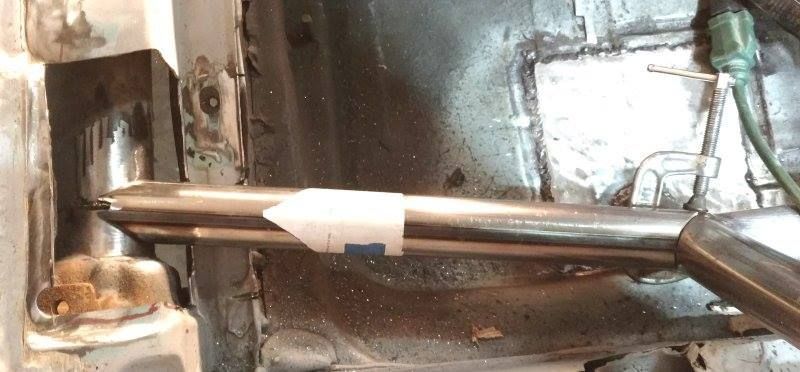
Here's the whole thing. I couldn't use bars across the car because I had very limited space across the top of the trans. As it was, I had to relieve it a little after this.


Here it is tested fitted during construction.

It was all trianglulated and brace. (Yes, I like speed holes.) The difference afterwards was like night and day. Instead of flexing all over the place the car stopped understeering and went exactly where you pointed it. On trailing throttle it would give you a neat, predicable oversteer on the dirt.

I was Awesome! Almost wish I'd kept it now. Although I will say, all that extra bracing and urethane mounts made it a lot more noisy inside the car.
That was with a 160hp btw, so I do think kafer bars help even on our 100hp cars.
Here they are...
Here's the whole thing. I couldn't use bars across the car because I had very limited space across the top of the trans. As it was, I had to relieve it a little after this.
Here it is tested fitted during construction.
It was all trianglulated and brace. (Yes, I like speed holes.) The difference afterwards was like night and day. Instead of flexing all over the place the car stopped understeering and went exactly where you pointed it. On trailing throttle it would give you a neat, predicable oversteer on the dirt.
I was Awesome! Almost wish I'd kept it now. Although I will say, all that extra bracing and urethane mounts made it a lot more noisy inside the car.
That was with a 160hp btw, so I do think kafer bars help even on our 100hp cars.
-
Ol'fogasaurus
- Posts: 17756
- Joined: Mon Nov 13, 2006 10:17 pm
Re: Rear suspension, engine, and trans. bracing points
No, I wasn't really talking about buggies so much as discussing the pan itself. You are right though that take away the body and there is nothing to transfer the pan loads around. The glass body is of minor help but most of them don't have the all important roof that would do that load transferring. It is up to a good cage design to do that work.
What you did and the change to your toy shows how important stiffening things up can be.
What you did and the change to your toy shows how important stiffening things up can be.
-
coolrydes
- Posts: 53
- Joined: Thu Oct 29, 2009 10:16 pm
Re: Rear suspension, engine, and trans. bracing points
It is funny when you guys build one part and assume all are the same. they are not, we tried it you low cost none engineered way. everything thing we design and make is that way because they need to be for both quality and performance.
Kevin "Coolrydes" Zagar
MENDEOLA SIGNATURE MOTORS

MENDEOLA SIGNATURE MOTORS
-
Ol'fogasaurus
- Posts: 17756
- Joined: Mon Nov 13, 2006 10:17 pm
Re: Rear suspension, engine, and trans. bracing points
Kevin, as I said, I like your bj truss design as it is well thought out and is stiff; more than usable in most having fun venues'.Ol'fogasaurus wrote: ↑Thu Feb 02, 2017 6:23 pm Pete, I agree with doing both... which is what I did. I run in rough territory which is why I did it that way.
The spot welds still allow movement in the formed metal join and can pop lose if the action gets too severe. I did a full seam weld on my buggy just to take any potential weakness out of the game.
Hard acceleration, a lot of torque, hard cornering and bouncing around can cause the cantilevered enine and tranny hanging out the back to move around appropriately to what is being done to them.
Mendola's design, for bj, has each brace working against each of the other braces tying everything together... stiffly. The triangle is the tying together of everything.
-
petew
- Posts: 3920
- Joined: Sat Oct 07, 2006 4:05 pm
Re: Rear suspension, engine, and trans. bracing points
Do you guys do great work? Absolutely. It's top notch. However, there's more to the equation....
1. Specs. Do I need something specced for a 300+hp drive train in my 150hp car? No.
2. Can I afford your U.S.$$$$ (+ shipping) components? No.
3. Will my $$$ homemade setup get me 80% of the benefits? Yes.
If, however you're happy to send me one of your setups for free, I would be happy to try it.