
Schematics, diagrams and shop drawings.

-
panel

- Posts: 4201
- Joined: Sun Sep 24, 2000 12:01 am
Anyone have a '72 Beetle wiring diagram for me to have a look at. This car I'm working on has 12 fuses on the block.
-Marc.
-Marc.
'65 Bus with a JDM Subaru EJ20 Turbo
Built by Germans powered by Japanese and brought together by Canadians
Built by Germans powered by Japanese and brought together by Canadians
-
shopteacher

- Posts: 714
- Joined: Fri Dec 29, 2006 9:58 am

-
david58

- Moderator
- Posts: 14096
- Joined: Sun Oct 23, 2005 6:14 pm
63 US Model Speedo Wiring

Typical Horn Wiring

3 switch master cylinder wiring

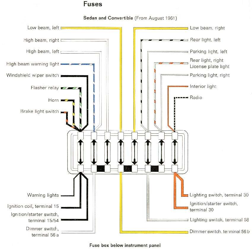
type3_61_fuses

Starter wiring

Bosch fog light relay wiring diagram

Early bay turn signal wiring diagram

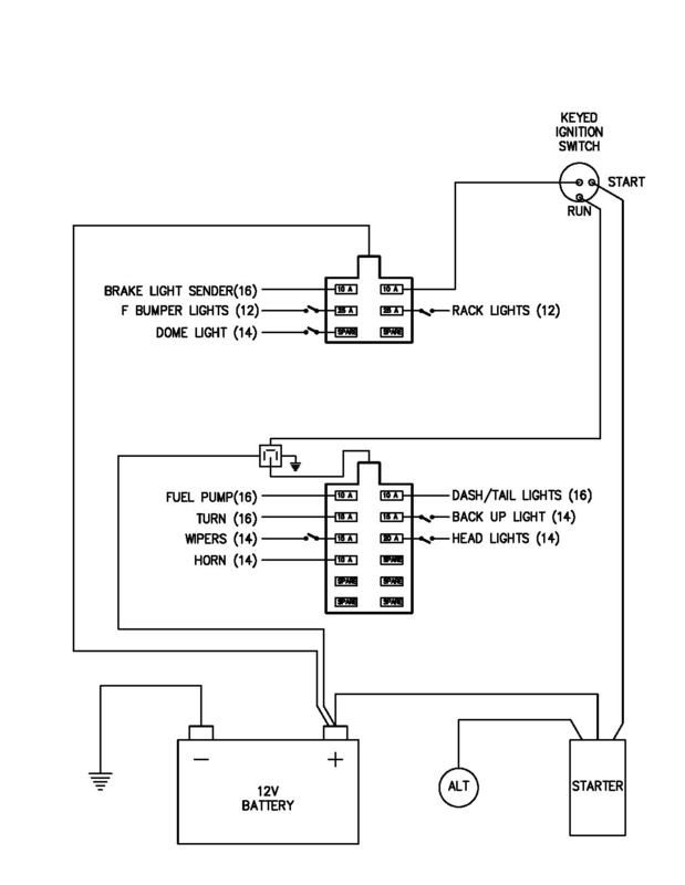
Baja Bug Wiring

Bus Emergency Light wiring from 8/1965

Fuel pump wiring

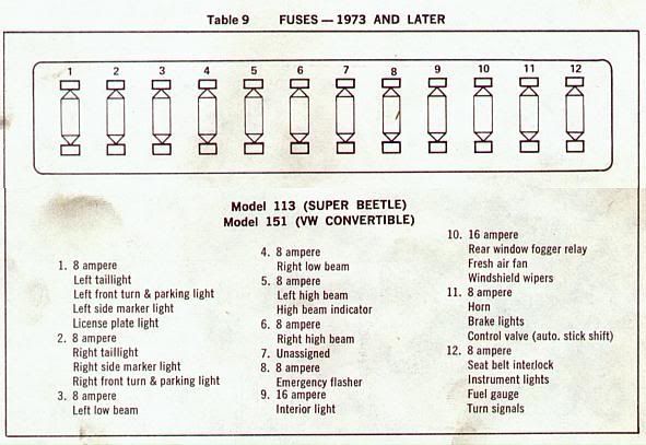
Speedometer Wiring Diagram for later Super Beetles and Convertibles.

Thing wiring diagram

Dual Battery wiring

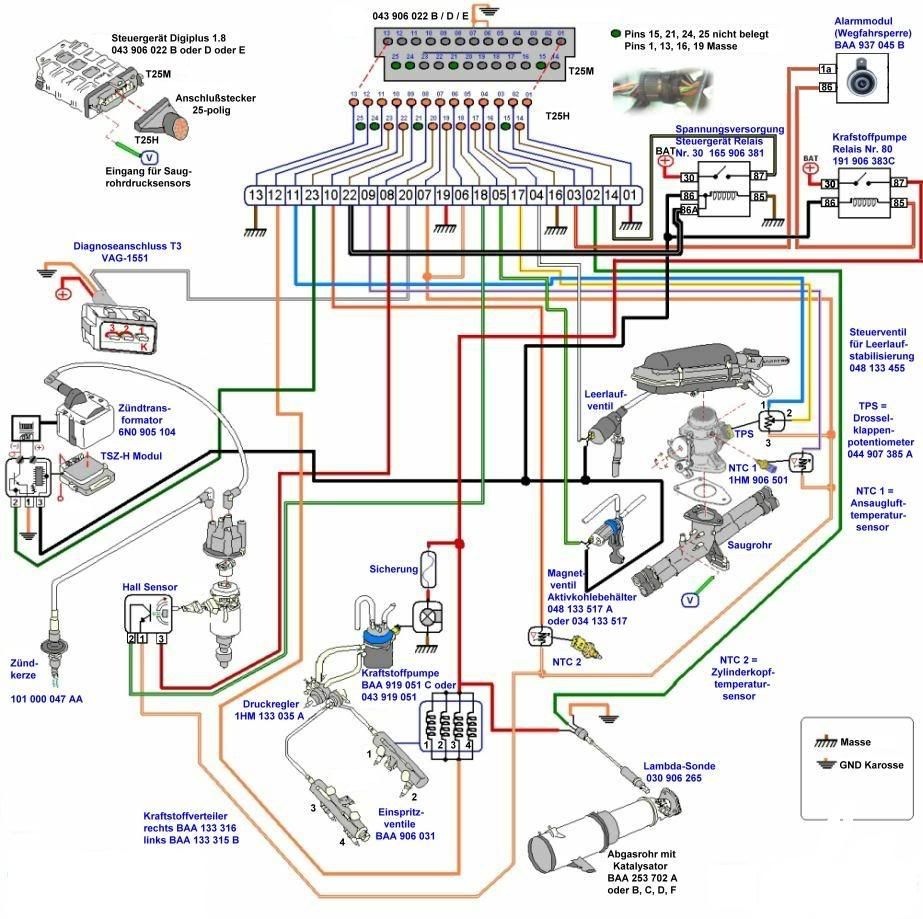
EFI wiring T3/4

bug wiring

1966 1300 Type 1 wiring diagram

Noco battery isolator wiring diagram
flyingCoyote
For charging a second battery while protecting the first from discharge (camping, radios, etc)

71 SB Wiring Diagram

This is a modified wiring diagram showing the alternator wiring for a conversion from externally regulated alternator or from a generator

Here is a short and sweet help with wiring a genrator and alternator. it includes the regulator wiring diagram


Portion of the 67 bus wiring diagram showing the engine compartment

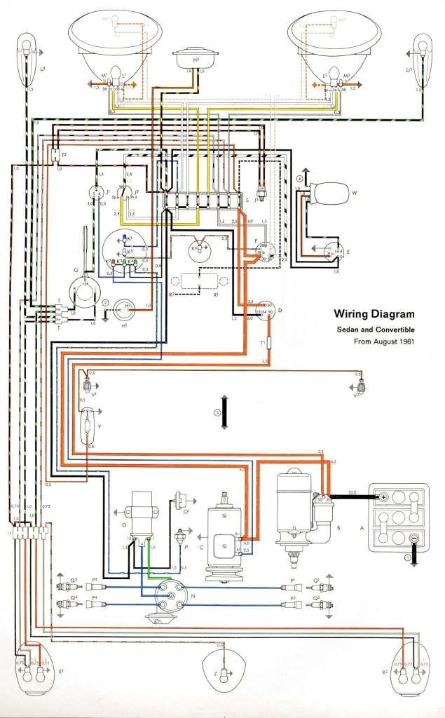
Full lifesize wiring diagram

Typical Horn Wiring
3 switch master cylinder wiring
type3_61_fuses
Starter wiring
Bosch fog light relay wiring diagram
Early bay turn signal wiring diagram
Baja Bug Wiring
Bus Emergency Light wiring from 8/1965
Fuel pump wiring
Speedometer Wiring Diagram for later Super Beetles and Convertibles.
Thing wiring diagram
Dual Battery wiring
EFI wiring T3/4
bug wiring
1966 1300 Type 1 wiring diagram
Noco battery isolator wiring diagram
flyingCoyote
For charging a second battery while protecting the first from discharge (camping, radios, etc)
71 SB Wiring Diagram
This is a modified wiring diagram showing the alternator wiring for a conversion from externally regulated alternator or from a generator
Here is a short and sweet help with wiring a genrator and alternator. it includes the regulator wiring diagram
Portion of the 67 bus wiring diagram showing the engine compartment
Full lifesize wiring diagram
Hot, humid air is less dense than cooler, drier air. This can allow a golf ball to fly through the air with greater ease, as there won't be as much resistance on the ball.
-
shopteacher
- Posts: 714
- Joined: Fri Dec 29, 2006 9:58 am
A-arm total car Suspension EXPLAINED

http://www.honkernet.net/AHS/department ... ension.htm
Rear pivots line up to point at either the differential or a central part on the transaxle (also known as the THIRD member)
straight line off the steering arm of the
spindle points to the same point on the trans that the rear pivots point at.
Steering arm length is determined by how much response you require in your steering wheel--shorter arms turn faster
Front spindle to rear axle length should be the same on both sides and camber set equal before adjusting toe in/out, set rear toe first
Bump steer can be eliminated or at least minimized by making sure all the arms and tie rods are parallel and the inner heim joins line up
Control arm attachment points line up with rack mounting points
and intersect on the center line of the chassis