Jerry...
69veedub wrote:If you scroll down you will see my dash
http://www.shoptalkforums.com/viewtopic.php?t=103716
Jeff
2088 bob wrote:tim brings up a very good point
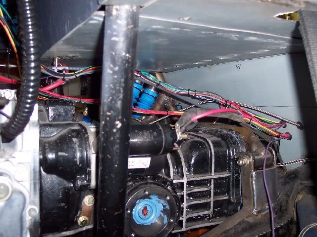
which now brings me to a subject i have been wanting to cover for quite some time especially with you guys building fiberglass buggies please direct your attention to the following picture
If you look very carefully at the bottom center of the pic you will see a really fat black wire going to a short little terminal strip
That is the ground buss ,the heavy wire feeding it is a 8ga wire good for 40 amps that wire goes right back to the negative post of the battery The wire feeding the power panel is also 8ga so now we have set
up the what goes in must come out scenario
every item that requires ground is hooked to that terminal strip which now assures a solid ground path back to the battery
this is the best way to handle grds in a glass car
fl_buggy wrote:I finally got around to the wiring on my rail buggy project. I'm doing some things that are a bit different so I figured I'd document them here.
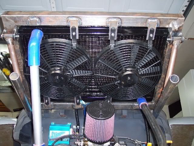
First, a bit of background on the car. The car is a woods buggy for trail riding in Florida. Function is of the utmost priority, and form isn't really in the picture muchThe car will be powered by a Type 4 motor with stock cooling and a home built exhaust. I'll be controlling the motor with a Megasquirt system using EDIS for ignition.
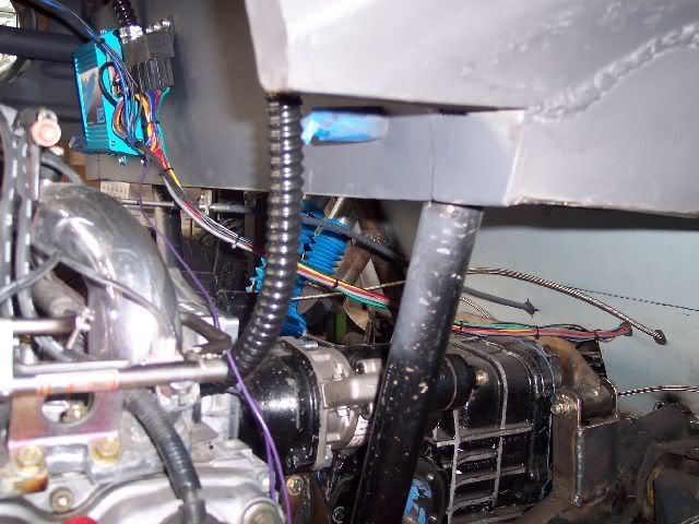
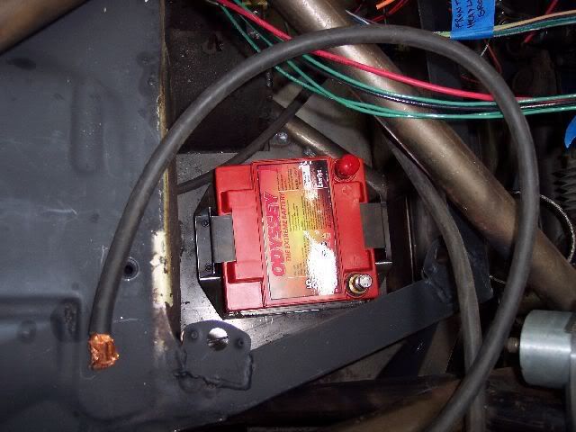
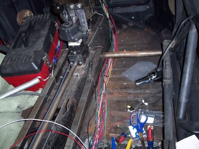
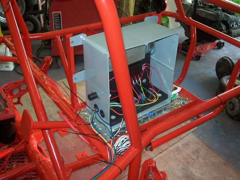
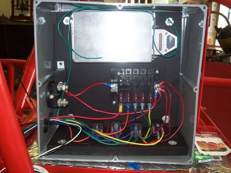
Because I'm running the MS, I needed a secure, dry, clean place to mount the ECU. On the advice of a guy on the MS forums, I decided to mount all of the electronics in a plastic electrical box from Lowes. The box ran about $40, but is plenty sturdy, big enough to fit everything with room to work, and has an o-ring seal on the lid. The first picture is an overview of the box mounted in the chassis. It sits up high, right behind the drivers seat, next to the fuel cell.
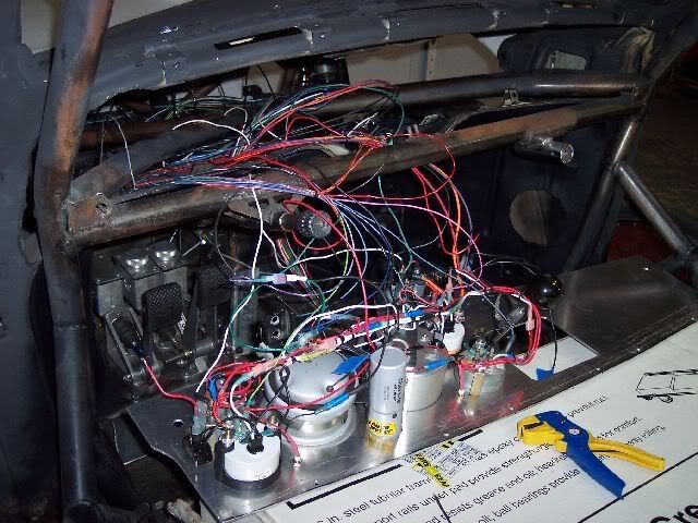
The next picture is a close-up of the inside of the electrical box. I built a platform from 3/4" birch plywood I got from work. I screwed it into an "L" shape, painted it black, and secured it to the back wall and bottom of the box using "T" nuts.
As you can see, the MS is mounted at the top of the box. Below that is a "marine" distribution block and fuse block (since the box is sealed, I didn't need a sealed fuse block so it was cheap). Below that is my row of relays. To the left is a master power switch which uses a red plastic church key to turn it on and off. Since this car won't be left alone very long, a church key is enough security.
One thing I did differently is to save a bit of wire, I am switching the ground on my relays. I saw on here that a few don't like the idea, but it works for me and since I'm the only one that will work on it, that's all that matters.
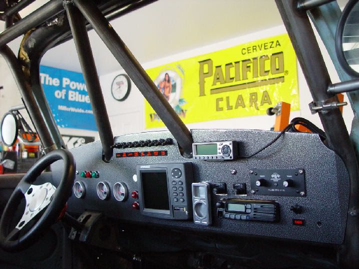
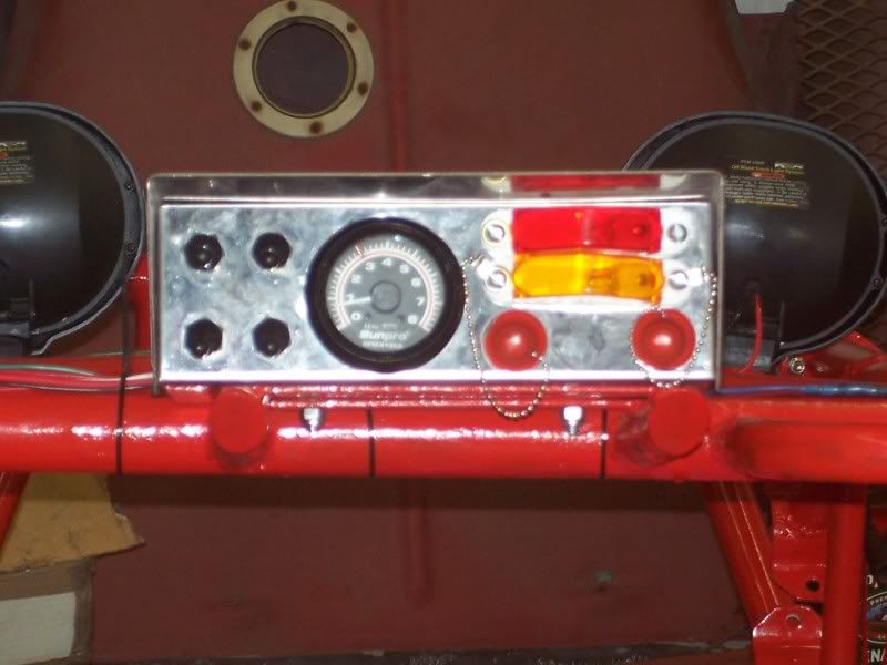
Moving to the front of the car, I'm using a generic stainless switch box that I got from Fisher Buggies here in Tampa. It was blank which is what I wanted, since I am doing things a bit different. Below is a pic of the finished dash.
Going from left to right, I have 4 CB Performance sealed toggle switches which are very nice for the money. 3 are regular on-off switches. The other is an off-ignition-start switch which I really like. Next over is a cheap simple tach a friend gave me. The price makes it worth it if the dirt and mud eat it up. Next, at the top are red and yellow trailer marker lights that I'm using for warning lights. I wanted something big and bright that I could see during the day. Below the lights are 2 cigarette lighters with some rubber caps to keep dirt out. I wanted 2 lighters since we have a Palm Pilot and GPS that we use for geocaching. The lighters are wired so they are only hot when the master power switch is on.
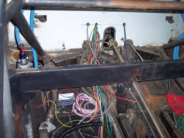
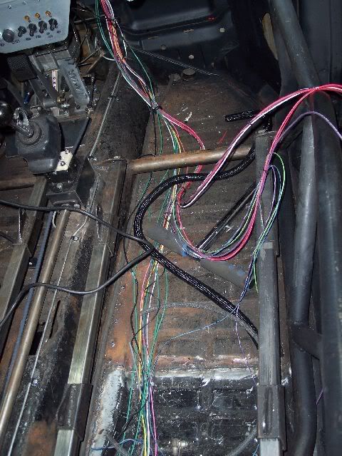
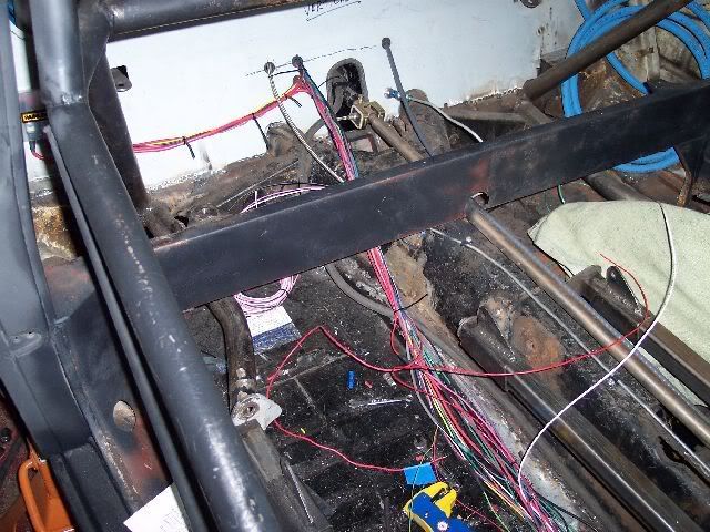
As you can see, all of the wiring was run on the outside of the chassis tubing. I did this because I know people that have taken the time to drill holes in the chassis to run the wiring through, only to chafe wires and cause shorts. I wanted to avoid that, and like I said, looks don't matter nearly as much as function. Plus, roll-bar padding will cover the wiring in the vulnerable areas.
Feel free to question, comment, or point out things you'd change.