Type 1 Wiring Diagrams - PIX Thread

Every car has an electrical system. Here's the place to learn all about it.
User avatar
david58
Moderator
Posts: 14096
Joined: Sun Oct 23, 2005 6:14 pm

Type 1 Wiring Diagrams - PIX Thread

Post by david58 »

3
1973 Fuse Panel
Image
4
How to Read 1973 Diagrams
Image
5
1972 Wiring Supplement
Image
6
1972 Wiring Diagram
Image
7
1972 1302 Wiring Diagrams
Image
8
Image
9
Image
10
Image
11
Image
12
1970 Wiring Diagrams
Image
13
Image
14
1969-1971 Wiring Diagrams
Image
15
1968-1969 Wiring Diagrams
Image
16
1967-1970 Wiring Diagrams
Image
17
1966 Wiring Diagrams
Image
18
1965-1966 Wiring Diagrams
Image
19
1962-1965 Wiring Diagrams
Image
20
Image
21
1960-1961 wiring Diagrams
Image
22
Image
Last edited by david58 on Wed Sep 23, 2009 7:42 pm, edited 1 time in total.
User avatar
Glenn
Posts: 5108
Joined: Fri Mar 09, 2001 12:01 am

Re: Type 1 Wiring Diagrams

Post by Glenn »

1974 Beetle
Image
Glenn
74 Beetle Specs | 74 Beetle Restoration | 2180cc Engine
"You may not get what you pay for, but you always pay for what you get"

http://www.DasVolks.com
User avatar
MNAirHead
Posts: 9570
Joined: Mon Sep 08, 2003 6:12 am

Post by MNAirHead »

Cool idea.. I"ll see if I have any of the missing ones

Stickified!
User avatar
david58
Moderator
Posts: 14096
Joined: Sun Oct 23, 2005 6:14 pm

Post by david58 »

==Design Error + Missing Fuse = Ignition Conductor==
This is a good place to link this thread. :wink:
Hot, humid air is less dense than cooler, drier air. This can allow a golf ball to fly through the air with greater ease, as there won't be as much resistance on the ball.
User avatar
david58
Moderator
Posts: 14096
Joined: Sun Oct 23, 2005 6:14 pm

Post by david58 »

23
1957 Wiring Diagrams

Image
24

Image
25

1955 Wiring Diagrams

Image
26

Image
27

1954 Wiring Diagrams

Image
28
Image
29


1953 Wiring Diagrams

Image
30

Image
Last edited by david58 on Wed Sep 23, 2009 7:38 pm, edited 1 time in total.
User avatar
david58
Moderator
Posts: 14096
Joined: Sun Oct 23, 2005 6:14 pm

Post by david58 »

Here is a pretty cool link it shows different circuit wiring instead of the whole diagram just click on the circuit ( Brakes, Coil, Fuel Gauge, Generator,
Headlights and Tail, Horn, Indicators, Oil Pressure Switch, Reversing, Starter, Wipers )and a diagram of that circuit will appear.
http://www.djheath.net/volkszone/vw_bee ... iagram.htm
Hot, humid air is less dense than cooler, drier air. This can allow a golf ball to fly through the air with greater ease, as there won't be as much resistance on the ball.
User avatar
MNAirHead
Posts: 9570
Joined: Mon Sep 08, 2003 6:12 am

Post by MNAirHead »

User avatar
Chip Birks
Posts: 4006
Joined: Wed Mar 12, 2008 5:59 pm

Re: Type 1 Wiring Diagrams - PIX Thread

Post by Chip Birks »

This is the diagram for a 60 bug, I noticed that it wasn't on here.
60 bug wiring diagram efi redone (1085x1500).jpg
You do not have the required permissions to view the files attached to this post.
User avatar
harryset
Posts: 360
Joined: Mon Mar 15, 2010 8:16 pm

Re: Type 1 Wiring Diagrams - PIX Thread

Post by harryset »

Nice post, thanks.

For those of you who have never delved into the arteries of your bug, I had to use three different wiring diagrams in order to get my electrics working right on my old '68. Never did figure out what wiring harness was in that car.
'72 Standard
"I am the proud owner of a "Hoover Bit".

185 60's, EMPI disc kit, EMPI 2 1/2" dropped spindles on the front.
185 65's and stock binders on the back.
SecondSkin - Damplifier Pro and Luxury Liner Pro for sound control.
User avatar
david58
Moderator
Posts: 14096
Joined: Sun Oct 23, 2005 6:14 pm

Re: Type 1 Wiring Diagrams - PIX Thread

Post by david58 »

Thing Wiring Diagrams
Captain Spalding wrote:Greetings all. Some of you may know that I have been working on some high-resolution versions of Thing wiring diagrams. I am happy to report that they are now available in the Samba Technical section. (Technical –> Wiring –> Thing)

I will use this thread to announce revisions when they are made available. Every effort has been made to make these documents as accurate as possible. I used original VW source documents where available. If you spot any typos, errors, omissions, etc. please notify me via private message and I will make the necessary changes. Please note that where the wire colors on my car, and possibly yours, differ from the source diagram, I deferred to the source diagram.

The impetus for this project was an electrical issue I had. I have seen many so-called Thing wiring diagrams, but many of them were inaccurate, incomplete, partially illegible, or not actually pertaining to the Thing. I found a pretty decent scan of a European-version current flow diagram, which actually had the 181 model number and date printed on it. I compared that to the lo-res "yellow" current flow diagram which has resided in the Technical section for a long time to confirm that the yellow diagram actually pertains to the Thing, and then I rebuilt it stick-by-stick in a vector-based drawing program, and saved it as a PDF file. If you don't know what that means let it suffice to say that you can zoom in as far as you need to to see the detail. I used the information in this diagram as a basis for the rest.

The documents (I'm just linking to the tech section. They're all there. Some of them are large, so please be patient.):

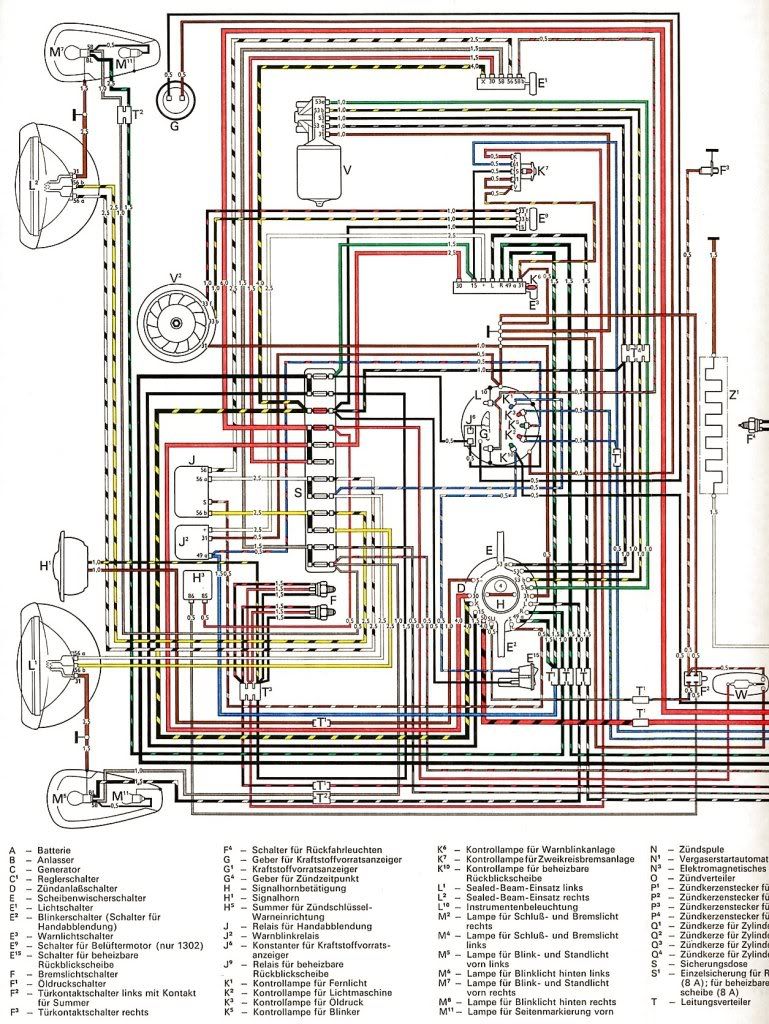
181_Current_Flow_Diagram_4-73.pdf
As I mentioned, a reasonably faithful PDF reproduction of a 181 current-flow diagram dated 4/73. It's the North American version, with the wire color change for the elephant ear tail lights and front turn signals with the shared bulb for turn signals and running lights, as well as the side marker lights. It also includes descriptions, which the "yellow" diagram lacks.

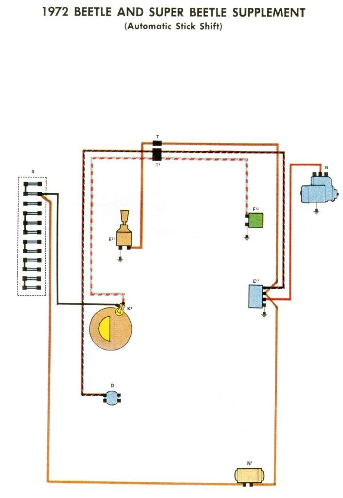
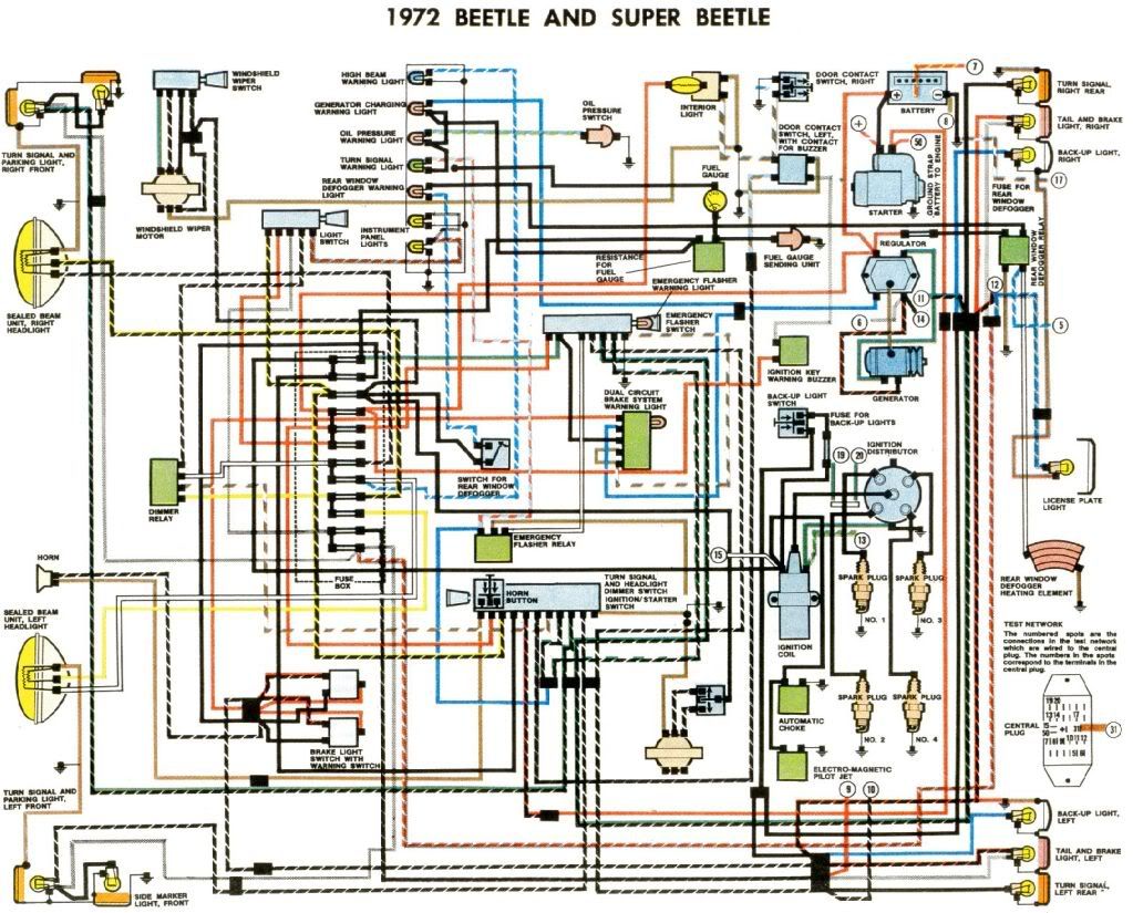
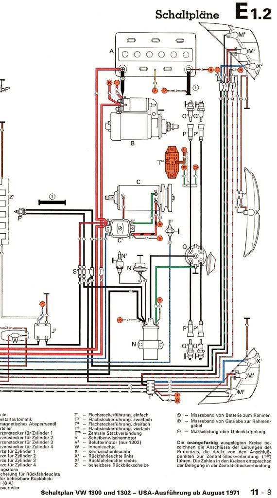
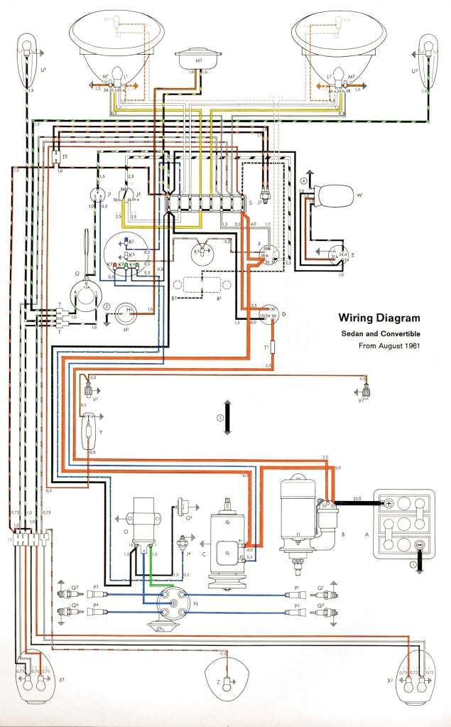
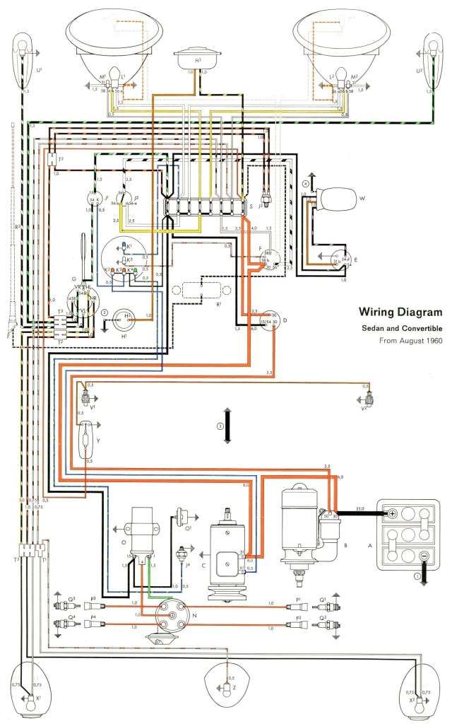
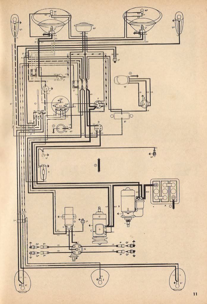
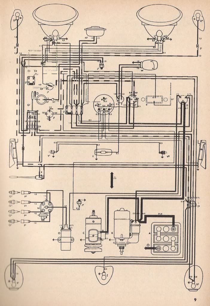
181_Wiring_Diagram_4-73.pdf
Many people find the current flow diagram to be a little daunting to decipher. This drawing is a translation of the current flow diagram into the more friendly component-based style, with pictographic representations of the electrical components roughly laid out as they are in the car. Again, it's a North American version, and includes elephant ear tail lights, the windshield wiper switch as a stalk on the column vs. a knob on the dash, etc.

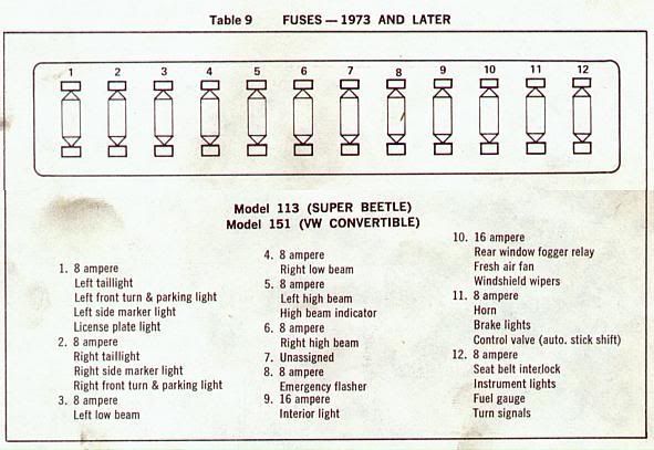
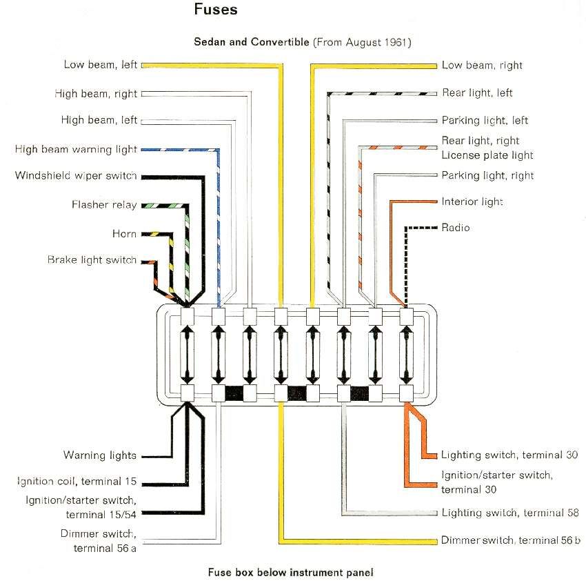
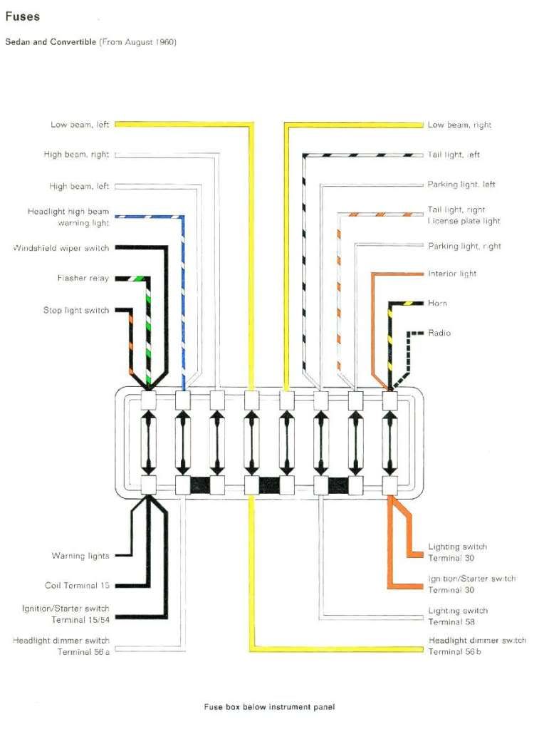
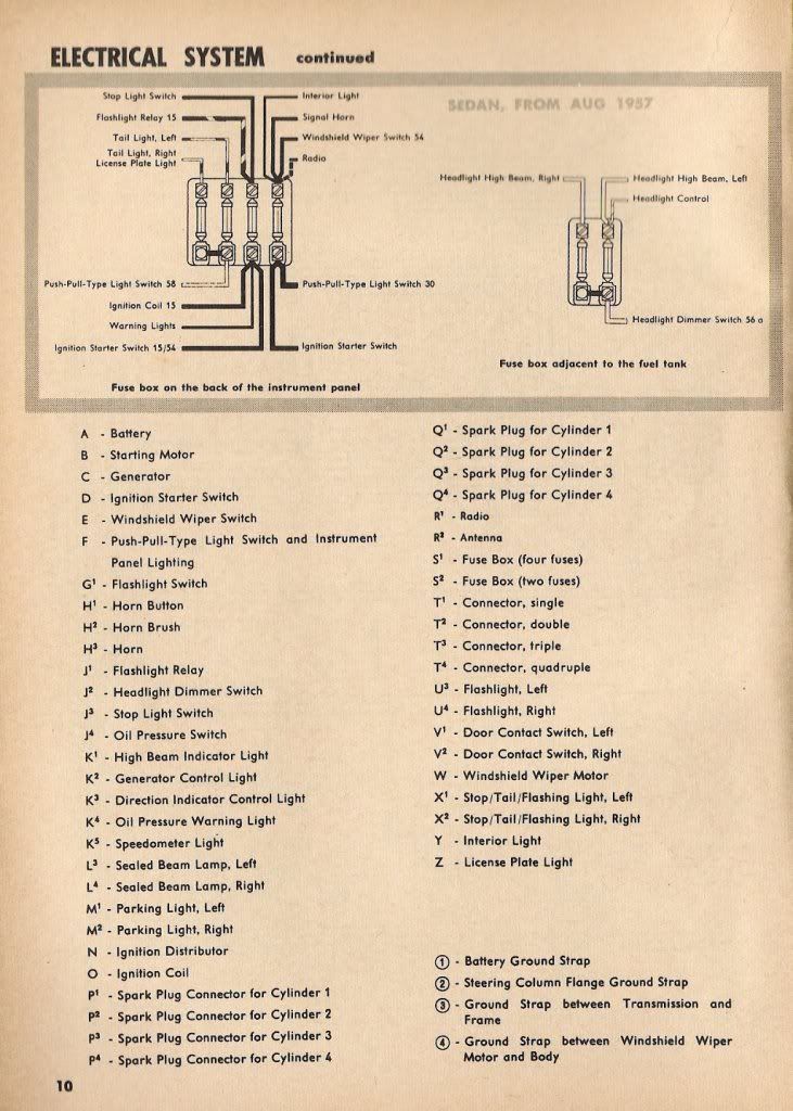
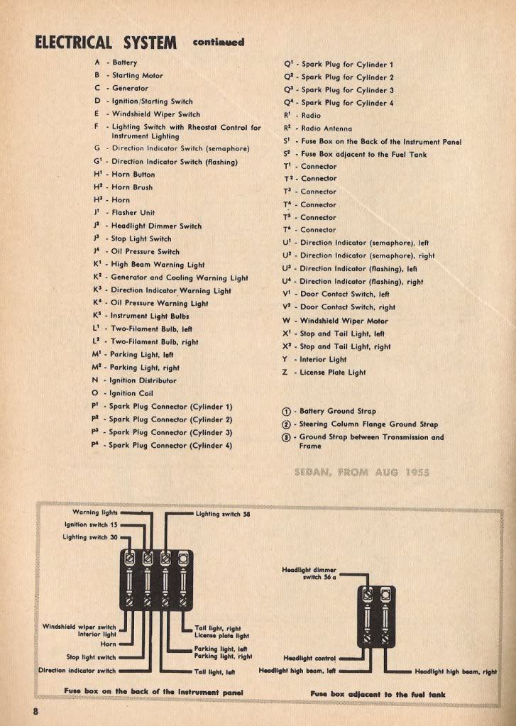
181_Fuse_Block_Wiring_Detail.pdf
Just what it says - a diagram of the Fuse Box showing fuse ratings, wire sizes and colors, and terminal information where appropriate. I have posted earlier versions of this diagram in various threads. If you downloaded a prior version, please trash it and use this one. The whole point of this exercise is to make the information as definitive as possible, and the last thing we need is old inaccurate versions circulating around. Prior versions are undated. These new diagrams have a date in light gray type in the lower right corner.

181_Tail_Light_Wiring_Detail.pdf
This drawing depicts the tail light wire colors as they change at the two 4-pin connectors in the engine compartment. This issue has come up several times on the board, so I thought it deserved its own drawing. As with the fuse block drawing, if you have a previous (undated) version, please trash it.

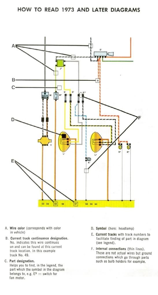
How_to_Read_Current_Flow.pdf
A concatenation of several pages which explain how to read current flow diagrams. For some reason, scans of those pages are rarely posted together, so I put everything on one page.

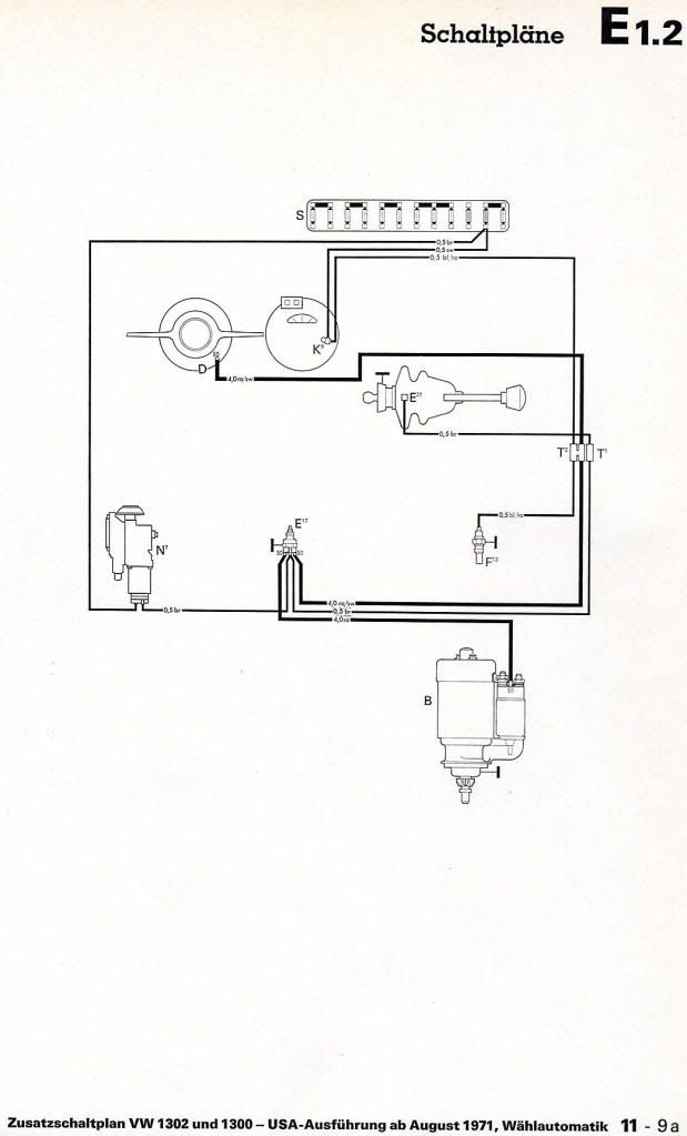
Pending releases: current flow and component-based wiring diagrams for the Eberspächer BN-4 heater.

I had loads of fun doing this project, and learned a lot. We all owe a HUGE thank you to tallman206, a fellow Samba member without whose proofreading and advice these drawings would not have been possible. Thanks also to Ian Epperson, Pierre G, and everyone else who answered all of my fool questions.

Cheers!
Wiring Diagrams Finished and Available
Hot, humid air is less dense than cooler, drier air. This can allow a golf ball to fly through the air with greater ease, as there won't be as much resistance on the ball.
vegasdude
Posts: 1
Joined: Thu Dec 29, 2011 12:56 pm

Re: Type 1 Wiring Diagrams - PIX Thread

Post by vegasdude »

hello every one, me and a frind of mine are working onmy 1978 vf superbeetle fuel injecion, we took the engine dwon to replace the cluth however, we dont remember where the censore that in by the flywell connects to and cant find any diagrams or books, thre is also a black single plug, i will apreciate in any one can guide me to the right direction please and also the the injectors are getting power on both wire,, like there is no grown,,,
Post Reply