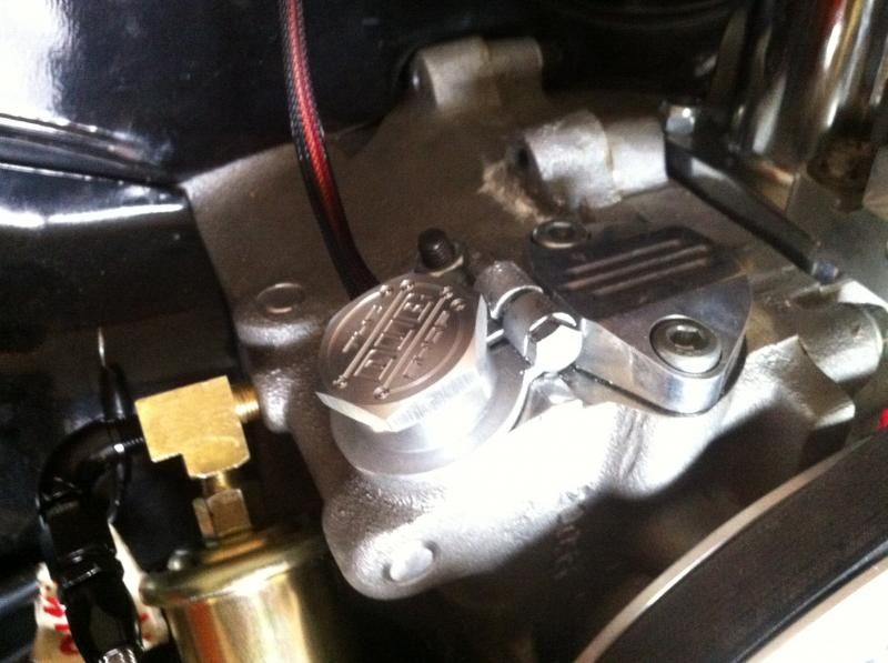
Mini Cam Sync

jhoefer
Posts: 195
Joined: Wed Oct 05, 2011 2:30 pm

Re: Mini Cam Sync

Post by jhoefer »

Camo wrote:Excellent stuff Chip. When you say the car fully synced up within a couple turns, do you need to position the cam sync in a particular spot like a distributor so the injector timing is spot on. I guess that the pickup inside needs to be timed or very close to the sweet spot so fuel is injected at the right time.

Sorry for my lack of knowledge, I'm new to EFI and just starting to fit my engine up with MS3x and will also be going full sequential fuel and ignition.

Good to see that Mario has started sending out the orders, I am looking forward to fitting my new engine up with one.

Cheers, Kev
The ECU can take a couple revolutions to sync because when it starts, it has no idea what position the motor is in. You need up to 1 rev for it to identify TDC on the crank and up to 1 more rev to identify #1 cylinder from the cam.

In the typical MS missing tooth crank/single tooth cam setup, it doesn't matter much where the cam tooth is in relation to the missing tooth on the crank, but you cannot have them overlap. For example, you could run the cam tooth 30-40 degrees before the missing crank tooth, that is, if the missing tooth is 90 degrees BTDC, you position the cam tooth signal pulse at 120-130 degrees BTDC. If you happen to set the cam such that the engine Syncs and it still won't fire, it's probably out of phase and incorrectly thinking #3 is #1, so you just add 360 degrees to the Tooth #1 Angle and try again.
Redline Weber

Mini Cam Sync = NOT "0" OR "360"

Post by Redline Weber »

You point is GREAT though you "miss" the more important item.

DO NOT set the CAS at "0" or "360" degrees.

When a "drift" occurs the Phase could switch between firing/overlap.

Lance
User avatar
Camo
Posts: 71
Joined: Wed Oct 24, 2007 5:55 pm

Re: Mini Cam Sync

Post by Camo »

jhoefer wrote: The ECU can take a couple revolutions to sync because when it starts, it has no idea what position the motor is in. You need up to 1 rev for it to identify TDC on the crank and up to 1 more rev to identify #1 cylinder from the cam.
Thank you. So the ECU works it out when to fire the fuel compared to the crank positioning. I thought the mini sync alone was telling the ECU when to squirt the fuel. I was also thinking you would need to turn the mini sync (outer section) to time the actually sensor within to be in the right position for TDC number 1 off the cam.

I'm just confusing myself more now :?

Cheers, Kev.
User avatar
Piledriver
Moderator
Posts: 22520
Joined: Sat Feb 16, 2002 12:01 am

Re: Mini Cam Sync

Post by Piledriver »

The confusion stems from there being two mini cam syncs being discussed
(one is in the works):

The std one (seen in the pics) has one tooth and is used for sync only, requiring a crank wheel for the main timing signal. (missing tooth or non missing tooth)
This may provide more accuracy on some setups, as you can run some pretty high tooth count wheels on MS3.

There is also a second version in the works with 12 base teeth, one missing tooth.
(Redline Weber calls this GEAR DOWN TW iirc)

A "legal" missing tooth wheel at cam speed (AKA distributor based) is all many ECUs need to run fully sequential.
(redline, ms2E, ms3, and probably most other reasonably modern aftermarket EMS)
Addendum to Newtons first law:
zero vehicles on jackstands, square gets a fresh 090 and 1911, cabby gets a blower.
EZ3.6 Vanagon after that.(mounted, needs everything finished) then Creamsicle.
Redline Weber

Mini Cam Sync Signal Position

Post by Redline Weber »

Your question, Camo, IS well founded, not discussed above.

Your logic is ALSO fine just understand you need to provide the ECU with an "advanced" report.

Thus the CAS event should be AFTER the last cylinder BUT before the first cylinder in the firing order.

MY method is to "time" the event at an EQUAL DISTANCE between those points.
NO NEED to "split hairs" because of the board range of degrees.

NOTE, this method works with "missing tooth" crankshaft wheels ONLY.

Lance
foreverska
Posts: 137
Joined: Tue Jun 18, 2013 11:24 am

Re: Mini Cam Sync

Post by foreverska »

jhoefer wrote:The ECU can take a couple revolutions to sync because when it starts, it has no idea what position the motor is in. You need up to 1 rev for it to identify TDC on the crank and up to 1 more rev to identify #1 cylinder from the cam.
Why is it not the other way around? Wait for the CPS and then try to identify the missing tooth afterwards? Keep a count of teeth after the CPS. If greater than half you're now on #3 in the timing order if less than half you're now on #1 in the order. I guess that assumes the CPS has only a minute adjustment compared to the crank which really should be true or else what should be a mark for #1 could be spun around and find itself marking 3. But this scheme does not care where the CPS is at all. It can be on top of the missing tooth, count 35 teeth and never miss a beat.
User avatar
Piledriver
Moderator
Posts: 22520
Joined: Sat Feb 16, 2002 12:01 am

Re: Mini Cam Sync

Post by Piledriver »

IIRC, with a non missing tooth crank wheel, on MSextra and ms3, the cps trigger flags the next crank tooth as tdc#1.

with a missing tooth crank wheel, the next missing tooth is TDC #1, cps setting up the missing tooth code loop ahead of time.

Seems to me the non missing tooth logic eliminates the missing tooth code loop, but at the loss of a fail safe.

The triggers edges not overlapping is likely a safe way so one doesn't miss a signal as easily.
(IIRC the timing signals drive hardware interrupts, it takes a ~uS or so to service the interrupt, and only one at a time)
Addendum to Newtons first law:
zero vehicles on jackstands, square gets a fresh 090 and 1911, cabby gets a blower.
EZ3.6 Vanagon after that.(mounted, needs everything finished) then Creamsicle.
jhoefer
Posts: 195
Joined: Wed Oct 05, 2011 2:30 pm

Re: Mini Cam Sync

Post by jhoefer »

foreverska wrote:
jhoefer wrote:The ECU can take a couple revolutions to sync because when it starts, it has no idea what position the motor is in. You need up to 1 rev for it to identify TDC on the crank and up to 1 more rev to identify #1 cylinder from the cam.
Why is it not the other way around? Wait for the CPS and then try to identify the missing tooth afterwards? Keep a count of teeth after the CPS. If greater than half you're now on #3 in the timing order if less than half you're now on #1 in the order. I guess that assumes the CPS has only a minute adjustment compared to the crank which really should be true or else what should be a mark for #1 could be spun around and find itself marking 3. But this scheme does not care where the CPS is at all. It can be on top of the missing tooth, count 35 teeth and never miss a beat.
I suppose you could, but you would still need up to 2 crank revolutions to sync since it may take one whole revolution of the cam to determine your #1 position (whether using dual wheels or single cam wheel). I suspect whatever code they actually use for dual wheel triggering probably started out of batch fire/wasted spark with a crank trigger only and then adapting that base code to full-sequential. That is, a crank trigger would be the base assumption, cam trigger would be a variation/special case. And as Piledriver mentioned, you'd still have the non-overlapping signal requirement on MS hardware due to the interrupt handling.
Redline Weber

Mini Cam Sync = NO Missing Tooth

Post by Redline Weber »

The question of a method by Foreverska has been used by MANY ECU manufactures that were NOT ABLE to "decode" my 60-2, 36-1 TW for years.
That method of using a CAS tooth to find home results in NO acceleration measurement of the crankshaft, an "event" driven ECU.
The Timing Lag result is the distance between the crank tooth count AND CAS event when the Spark Instant is given in that area.
When the CAS event is lower than the Spark Instant Timing Lag can be up to two revolutions.
This is dependent on crankshaft acceleration, a steady state crankshaft RPM will show little change.

Thus when one relies on an EMS that needs a CAS to operate, BE AWARE of Timing Lag.

There is an easy method to check for Timing Lag :

LOCK Spark Advance to a FIXED Value, change RPM quickly both up/down, then read that advance value with a timing light.

Lance
foreverska
Posts: 137
Joined: Tue Jun 18, 2013 11:24 am

Re: Mini Cam Sync

Post by foreverska »

Got mine today cant wait to put it in but it's crunch time for my other project and the last thing I need is more sensors. :D So it's going to have to wait a few weeks. Fine looking product none the less.

Image
User avatar
Camo
Posts: 71
Joined: Wed Oct 24, 2007 5:55 pm

Re: Mini Cam Sync

Post by Camo »

Hi all,

well I have my cam sync (Thanks Mario) and its in, but now just trying to work out all of my wiring.

Just quickly, I have MS3x and also running the MS relay board.

With all the reading I have confused myself with which pin this mini cam sync is to be connected to. Going off the MS manuals it says that the cam input is pin 32 for MS3x. In different parts of the manual I think they also call it a cam input, crank input and tach input.

Here they call it the 'cam tach' input http://www.msextra.com/doc/ms3/ignition.html#tachext
I thought the 'tach' input was the sensor off the crank. No wonder a bloke gets confused :lol:

Please Confirm - If I am now thinking right, I believe the Tach input from my crank angle sensor actually goes to the relay board Pin 15 being the Tach circuit and the mini cam sync goes to pin 32 on MS3x. This then leaves pin 26 on MS3x as the output to run my tacho (rev counter) on dash.

Have I got this right or am I a lost cause :oops:

Thanks, Kev

Image
User avatar
MarioVelotta
Posts: 4083
Joined: Wed Mar 12, 2003 12:01 am

Re: Mini Cam Sync

Post by MarioVelotta »

You had it correct, pin 32 on the expander. Make sure you adjust the input pots for a Hall sensor.

This link may help.

http://www.diyautotune.com/catalog/18-m ... p-454.html

That's a good pic of an installed mini cam sync! Mind if I use it?
The Dub Shop
[email protected]
1600 ITB NA - 18sec
1600 Supercharged - 13psi - 15.40 @ 84.66mph
1600 Turbo - 185hp 250tq!! Going for 200
2276 Turbo - 15psi - 11.537 @ 115.74mph
Facebook-Tech-Store
modernbeat
Posts: 15
Joined: Sun Jul 13, 2014 7:13 am

Re: Mini Cam Sync

Post by modernbeat »

Mario, have you got this setup to be used to supplement the crank signal, or in lieu of a crank signal?

I first thought it was just a binary signal that would be used in conjunction with the crank position sensor to add sequential ability, but after a couple other posts, I'm not sure.
Jason McDaniel
User avatar
Camo
Posts: 71
Joined: Wed Oct 24, 2007 5:55 pm

Re: Mini Cam Sync

Post by Camo »

No worries Mario, please use that photo.

modernbeat wrote:Mario, have you got this setup to be used to supplement the crank signal, or in lieu of a crank signal?

I first thought it was just a binary signal that would be used in conjunction with the crank position sensor to add sequential ability, but after a couple other posts, I'm not sure.
Also as modernbeat says, this mini cam sync isn't to replace the cranks angle sensor, is it. I also thought it is to work in conjunction with it.

Is that correct ????

Mario, I looked at the link you posted and the list of pin outputs/inputs but nowhere does it say 'tach' input so where does the crank angle sensor connect to. Can anyone else answer this.

Thanks, Kev
User avatar
MarioVelotta
Posts: 4083
Joined: Wed Mar 12, 2003 12:01 am

Re: Mini Cam Sync

Post by MarioVelotta »

modernbeat wrote:Mario, have you got this setup to be used to supplement the crank signal, or in lieu of a crank signal?

I first thought it was just a binary signal that would be used in conjunction with the crank position sensor to add sequential ability, but after a couple other posts, I'm not sure.
This one just supplements the crank signal. It is still needed. If you have a trigger wheel at cam speed then you could omit the crank trigger.
Camo wrote:Mario, I looked at the link you posted and the list of pin outputs/inputs but nowhere does it say 'tach' input so where does the crank angle sensor connect to. Can anyone else answer this.
Crank sensor still goes to the main board, or tach on the relay board.
The Dub Shop
[email protected]
1600 ITB NA - 18sec
1600 Supercharged - 13psi - 15.40 @ 84.66mph
1600 Turbo - 185hp 250tq!! Going for 200
2276 Turbo - 15psi - 11.537 @ 115.74mph
Facebook-Tech-Store
Post Reply