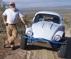
Dusty, you asked for dimension, maybe these will help; the spreader bar is sitting on the body mount part of the forging and the forward face is centered over the body mount fastener hole:
The blue line (rounded off dimensionally) is 10". The red line rounded off is 7 3/4".
Lee
Ol'fogasaurus black buggy
-
Ol'fogasaurus
- Posts: 17756
- Joined: Mon Nov 13, 2006 10:17 pm
Re: Ol'fogasaurus black buggy
You do not have the required permissions to view the files attached to this post.
-
dustymojave
- Posts: 2312
- Joined: Mon Dec 01, 2008 9:08 pm
Re: Ol'fogasaurus black buggy
Actually I was asking for dimensions of the body shell, Lee.
And don't go running off on account of me. Like you, I like to teach what I have learned. And I know far better than most (especially most of those who have purported to be my teachers) that there are a million ways to skin a cat, in this case, that cat being a fiberglass body buggy. And I also know VERY WELL that many of those million ways will work just fine. Don't think I'm telling you that you are "wrong". I'm suggesting another way than what you have in your mind is all.
And don't go running off on account of me. Like you, I like to teach what I have learned. And I know far better than most (especially most of those who have purported to be my teachers) that there are a million ways to skin a cat, in this case, that cat being a fiberglass body buggy. And I also know VERY WELL that many of those million ways will work just fine. Don't think I'm telling you that you are "wrong". I'm suggesting another way than what you have in your mind is all.
Richard
Lake LA, Mojave Desert, SoCal
Speed Kills! but then...So does OLD AGE!!
Tech Inspection: SCCA / SCORE / HDRA / ARVRA / A.R.T.S. OffRoad Race Tech - MDR, MORE, Glen Helen BajaCup
Retired Fabricator
'58 Baja with 955K Miles and counting
Lake LA, Mojave Desert, SoCal
Speed Kills! but then...So does OLD AGE!!
Tech Inspection: SCCA / SCORE / HDRA / ARVRA / A.R.T.S. OffRoad Race Tech - MDR, MORE, Glen Helen BajaCup
Retired Fabricator
'58 Baja with 955K Miles and counting
-
Ol'fogasaurus
- Posts: 17756
- Joined: Mon Nov 13, 2006 10:17 pm
Re: Ol'fogasaurus black buggy
Not sure what dimensions you are looking for. The body is a bit different in the rear so I have to do some FG work on that. Again, this was taken when I had a Cologne V6 in it that was tied to an 091.dustymojave wrote: ↑Wed Mar 14, 2018 3:39 pm Actually I was asking for dimensions of the body shell, Lee.
Other than that the lower body ends at the back of the pan which is a bit in front of the rear wheel fenders. This is an old picture but is gives you an idea of the rear of the buggy.
This is that upper tray I have been talking about. You can see the capped opening in the tray that I added where the fuel tank inlet would bee; open up the cover and the fuel tank cap is intended to be just below that leve.
Again, an old picture but the end of the transaxle is just a bit inside and below the Horseshoe cut out in the back of the body.
This is when I had a V6 in it but it should give you an idea of where the end of the pickle forks are in ralationship to the body.
There is plenty of room as long as it is used wisely.
Does this help?
Lee
You do not have the required permissions to view the files attached to this post.
-
Ol'fogasaurus
- Posts: 17756
- Joined: Mon Nov 13, 2006 10:17 pm
Re: Ol'fogasaurus black buggy
Dusty asked me a question a while back that I didn't answer as it was kind of complicated and I didn't have measurements. That question was how much room did I have in the new Truss/Kaffer bar design to the drive axle I was working on.
Ok, this is the buggy with trans and no engine or passengers. The trans is a stock bug transaxle with drive flanges that will be able to use a Type II or 924/944 CV joint. The spring plate is notched 1/4" and, as you see it here, the revised preload on the torsion of 24° (I think that is what I set it at but it was so long ago) so the spring plates, as the picture shows, is sitting on the stops.
The tires shown here are 30" dia. which is the same dia. as the Desert Tracs I will be running. I will keep the stock bump stops so that even with some compression on a hard hit I should be OK keeping the tires and the fenders apart. The max angle of the Bus CV joint is something like 17° but in the following pictures the axle angle is ~20 degrees. I have been using a similar setup (091 trans and bus CVs) for many years not so I think I am OK
I just took these today.
This is a 1 X 2 rectangular tube for the spreader and I was using a piece of 1" square tubing to get some measurements between the bottom of the tube and the rubber boot. The measurement in all three pictures it to the second rib of the CV boot.
In this setup I have a ~ 2 finger clearance at full hand. That comes out to about 1 1/2"s. The measurement is going to be off a bit due to the measuring of an over sized square tube as there would probably be some additional room when compared to a round smaller dia. tube for the clevises'.
By moving the connection to the spreader up higher on the rectangular tube I get a ~2" clearance.
By going back to the 1 X 3 rectangular tube I get ~2 1/2" of clearance at full droop. I didn't have anything long enough to get a good measurement so I used some string. This makes the measurement a bit off but close enough for an idea of what is going on.
I haven't pulled the torsion bar out to see what full compression will do but that will have to be done before too long... before I go and get a chunk of 1/8" wall rectangular tube... most likely 1 X 3. Being that the measurement to the boot was so close to the CV I am not sure just how much of gap to the axle to expect on full compression. Being that the axle is traveling in two arcs simultaneously is going to be interesting.
I might be able to accomplish it without pulling the torsion bar by using the tool for setting the preload; don't know yet. Too tired from what has been going on here for the last few weeks.
Anyway, part of the answer (I hope) to Dusty's question.
You do not have the required permissions to view the files attached to this post.
-
dustymojave
- Posts: 2312
- Joined: Mon Dec 01, 2008 9:08 pm
Re: Ol'fogasaurus black buggy
I doubt that using the spring plate installation tool will compress the suspension fully Lee. But those pics help me a lot to understand what you're dealing with.
I personally would have built a structure something like what Dave46 showed last page in his yellow Manx-style buggy, but adjusted to fit your T-Tub buggy body. Bring it back from the shock towers to a cross member above the bell housing. With the back braces of the roll bar coming down to flanges at the back edge of that rear "shelf" and angling down under the shelf to that cross member. Then braces down from that to the motor mount saddle. The gas tank would still mount much like how you are doing it and in the same location. I think that 2 cross support bars of .095 wall would be plenty, instead of 1 out of .120 wall. Or possibly the one cross bar with 2 bars fore and aft from that cross bar to the torsion housing so that the gas tank straps would mount to the fore/aft bars.
I personally would have built a structure something like what Dave46 showed last page in his yellow Manx-style buggy, but adjusted to fit your T-Tub buggy body. Bring it back from the shock towers to a cross member above the bell housing. With the back braces of the roll bar coming down to flanges at the back edge of that rear "shelf" and angling down under the shelf to that cross member. Then braces down from that to the motor mount saddle. The gas tank would still mount much like how you are doing it and in the same location. I think that 2 cross support bars of .095 wall would be plenty, instead of 1 out of .120 wall. Or possibly the one cross bar with 2 bars fore and aft from that cross bar to the torsion housing so that the gas tank straps would mount to the fore/aft bars.
Richard
Lake LA, Mojave Desert, SoCal
Speed Kills! but then...So does OLD AGE!!
Tech Inspection: SCCA / SCORE / HDRA / ARVRA / A.R.T.S. OffRoad Race Tech - MDR, MORE, Glen Helen BajaCup
Retired Fabricator
'58 Baja with 955K Miles and counting
Lake LA, Mojave Desert, SoCal
Speed Kills! but then...So does OLD AGE!!
Tech Inspection: SCCA / SCORE / HDRA / ARVRA / A.R.T.S. OffRoad Race Tech - MDR, MORE, Glen Helen BajaCup
Retired Fabricator
'58 Baja with 955K Miles and counting
-
dustymojave
- Posts: 2312
- Joined: Mon Dec 01, 2008 9:08 pm
Re: Ol'fogasaurus black buggy
Where you drew the rear braces (using Paint) in the side view a few pages back, where would those rear roll bar braces pass through the fiberglass?
Those fore/aft braces for the gas tank I mentioned in my last post would meet the torsion housing probably just outboard of the IRS brackets. They would probably be straight tubes, maybe square tube.
Those fore/aft braces for the gas tank I mentioned in my last post would meet the torsion housing probably just outboard of the IRS brackets. They would probably be straight tubes, maybe square tube.
Richard
Lake LA, Mojave Desert, SoCal
Speed Kills! but then...So does OLD AGE!!
Tech Inspection: SCCA / SCORE / HDRA / ARVRA / A.R.T.S. OffRoad Race Tech - MDR, MORE, Glen Helen BajaCup
Retired Fabricator
'58 Baja with 955K Miles and counting
Lake LA, Mojave Desert, SoCal
Speed Kills! but then...So does OLD AGE!!
Tech Inspection: SCCA / SCORE / HDRA / ARVRA / A.R.T.S. OffRoad Race Tech - MDR, MORE, Glen Helen BajaCup
Retired Fabricator
'58 Baja with 955K Miles and counting
-
Ol'fogasaurus
- Posts: 17756
- Joined: Mon Nov 13, 2006 10:17 pm
Re: Ol'fogasaurus black buggy
Since the body has been off for a while I am not sure so I made an educated guess.dustymojave wrote: ↑Sun Mar 18, 2018 11:05 pm Where you drew the rear braces (using Paint) in the side view a few pages back, where would those rear roll bar braces pass through the fiberglass?
Those fore/aft braces for the gas tank I mentioned in my last post would meet the torsion housing probably just outboard of the IRS brackets. They would probably be straight tubes, maybe square tube.
Before I took the body back off I was looking to see if rear seats could be added hence the picture (the answer is NO!
This is the 1 X 2 tube I was playing with but now I am back to a 1 X 3 X 0.12 wall tube I have to buy (the thickest wall tube where I get my steel and AL carries). The left end of the tube is slightly cut off in the pix but other photos will show the relationship. The center of the beam is marked with CL and the supposed mounts for the fuel tank are shown as is the mount for the truss tube. For the rear mount of the tank mount I am thinking it will have to go onto the trans mount where the strap and the rear truss mount will be. I think there is going to be a very complicated pair of mounts that will have to be made assuming it can be done.
For the fuel tank mounts I was planning on using a thick wall angle iron (I think the material is 1/8") then diagonal brace it to support the weight of the fuel and the sloshing around of it too. (as a side note: I would like to change the fuel distribution spud of the fuel tank also as I do like to "side hill" a lot so a pair of diagonal tubes from the ends of the tank to the lengthened spud and maybe a pair from the center but up higher up on the tank [for up and down hills] might be a good idea but hopefully if the fuel gets that low I get back to camp before it. That is the main reason I had a fuel gauge sender added years ago.)
I think the down brace of the cage is going to be very close to the truss bar locations. Your idea to spread them out more (a while back) was a good point as it is going to make the transfer of loading go into the cage a bit easier due to the close joining of the components.
I have been too busy recouping from some work at my step-daughter's place (I am getting old
You do not have the required permissions to view the files attached to this post.
-
Ol'fogasaurus
- Posts: 17756
- Joined: Mon Nov 13, 2006 10:17 pm
Re: Ol'fogasaurus black buggy
This is what I think the load transfer might be like (I hope !). The red is the truss bars, the white is the cage w/down bars while the black it the lowing up and down; a push/pull situation.
You do not have the required permissions to view the files attached to this post.
-
Ol'fogasaurus
- Posts: 17756
- Joined: Mon Nov 13, 2006 10:17 pm
Re: Ol'fogasaurus black buggy
Dusty asked the question about axle travel at full compression and the distance then to the Kaffer/truss bar. I was wondering about that myself so today I got out into the garage and made an attempt to find out.
First, this is a mod I made to my tool for setting the preload and that was to add 2 washers to smooth the tightening. 1 worked OK but two worked better.
The second thing I did was to replace the winged nut with a better quality nut then use the winged nut as a jam nut when preloading the spring plate. This is a safety thing as I have two of these and both of them have had the winged nut start running back down the threads. the better quality nut haven't. Mine takes a 1 1/8th box end (for safety) to wind it up and down the threads.
The next thing was to add a bolt into the hole for the body to attach to on the forging. It probably doesn't need to bolt down, just sit there as it is the head that the tool fits over that keeps it from jumping off the forging. A threaded bolt surely would be better.
This is not something I really like to do this way. Turning the suspension up not just the spring plate bothers the heck out of me mostly because of the added weight to the torsion resistance! I do not recommend this as I am not sure just how strong the bar or it's threads are. I have seen the bar bend under load so for what it is worth... I would prefer to work with the spring plate only, not with the suspension attached. I lubed the nut and threads before starting the climb to what seemed like eternity .
.
This is the start of the wind up. The hollow head of the tool over the nut and the hook at the bottom part of the tool has a slot for the spring plate to fit in. Fit everything in place then tighten the nut up finger tight then thread on the winged bolt just below it.
I wound the tool up to a place where I got a very uncomfortable feeling so I stopped. I had two shop stools with me, a commercial one and the one I made. As I climbed up the threads I moved from one stool to the other to stay away from any possible flying around of things.
When the nut and the winged nut got too far apart, say a half and inch I moved the winged nut up to a 1/4" away then continued to wind the main nut up. As you can see the stop is not in contact but I did keep measuring the distance from the tube to the rubber CV cover and at this point it was an inch and a half away. At full compression with some pinching up of the rubber stop I think the distance from the truss bar to the boot would still have left ~1/2" or better.
When I started backing things down I did get a jam where the suspension would not come down and the nut was free. I backed it up to about 3/16" with the jam nut about the same distance below it then tapped way on the suspension with a rubber mallet. I did come loose but did not cause the nuts to back down. Gotta be careful with these things!
So far I haven't talked myself out of the spreader bar concept I am playing with but it has been interesting as one throws in each new attachment. Right now it is the room for the fuel tank rear mount to the engine mount along with the truss bar mount and still leaving room for the top strap of t he mount itself.
Lee
First, this is a mod I made to my tool for setting the preload and that was to add 2 washers to smooth the tightening. 1 worked OK but two worked better.
The second thing I did was to replace the winged nut with a better quality nut then use the winged nut as a jam nut when preloading the spring plate. This is a safety thing as I have two of these and both of them have had the winged nut start running back down the threads. the better quality nut haven't. Mine takes a 1 1/8th box end (for safety) to wind it up and down the threads.
The next thing was to add a bolt into the hole for the body to attach to on the forging. It probably doesn't need to bolt down, just sit there as it is the head that the tool fits over that keeps it from jumping off the forging. A threaded bolt surely would be better.
This is not something I really like to do this way. Turning the suspension up not just the spring plate bothers the heck out of me mostly because of the added weight to the torsion resistance! I do not recommend this as I am not sure just how strong the bar or it's threads are. I have seen the bar bend under load so for what it is worth... I would prefer to work with the spring plate only, not with the suspension attached. I lubed the nut and threads before starting the climb to what seemed like eternity
This is the start of the wind up. The hollow head of the tool over the nut and the hook at the bottom part of the tool has a slot for the spring plate to fit in. Fit everything in place then tighten the nut up finger tight then thread on the winged bolt just below it.
I wound the tool up to a place where I got a very uncomfortable feeling so I stopped. I had two shop stools with me, a commercial one and the one I made. As I climbed up the threads I moved from one stool to the other to stay away from any possible flying around of things.
When the nut and the winged nut got too far apart, say a half and inch I moved the winged nut up to a 1/4" away then continued to wind the main nut up. As you can see the stop is not in contact but I did keep measuring the distance from the tube to the rubber CV cover and at this point it was an inch and a half away. At full compression with some pinching up of the rubber stop I think the distance from the truss bar to the boot would still have left ~1/2" or better.
When I started backing things down I did get a jam where the suspension would not come down and the nut was free. I backed it up to about 3/16" with the jam nut about the same distance below it then tapped way on the suspension with a rubber mallet. I did come loose but did not cause the nuts to back down. Gotta be careful with these things!
So far I haven't talked myself out of the spreader bar concept I am playing with but it has been interesting as one throws in each new attachment. Right now it is the room for the fuel tank rear mount to the engine mount along with the truss bar mount and still leaving room for the top strap of t he mount itself.
Lee
You do not have the required permissions to view the files attached to this post.
-
Ol'fogasaurus
- Posts: 17756
- Joined: Mon Nov 13, 2006 10:17 pm
Re: Ol'fogasaurus black buggy
The question of why did I suddenly get into change mounting methods
is kind of simple but at the same time a bit confusing. If you notice, the stock Truss/Kaffer bar kit I had bought had the spherical rod ends laying flat and that is mostly (I think) because of a VW engine compartment is cramped. If you look at the above pictures my glass buggy has a lot of room to play with. I got stuck thinking in a cramped situation (I apologize for that) so I was playing that out. This is not to say that I may not go back to that at least to the bottom connection but for right now I am trying to look at what I have to work with. The engine mount connection along with the fuel tank connection is a big deal which involves a lot of bits and pieces.
Also notice on the spreader beam I have marked the width of the fuel tank mounts. When I was a kid I was given a tank similar to this to carry for some distance; it was partly full of a liquid and I remember if I carried the tank with my arms close to the center so when the liquid sloshed around I almost dropped the load. When I got my arms moved out towards the ends it was easier to control even when the sloshing was still going on. It's funny but I can still feel that now days when I think about it. That is why the mounts on the tank are at full width and the marks on the stretcher bar accommodate the same spread.
I haven't done any design work with spherical rod ends since sometime in the 70's and maybe into the early 80's so it was put into a dark corner in my mind. Laying the rod ends flat has both good and bad points the bad points being that up and down movement can be blocked by mounts, et al, very easily. Also, like anything else, straight lines are stronger that changing directions especially when the design pieces you are working with have limitations hence it is stronger to have double shear mounts. The fasteners then are not taking most of the load especially if at the lengths you can easily get only give you a fully threaded bolt rather than having a shank to absorb some of the loading.
As you rotate the spherical rod end connections towards a vertical connections some of the limitations start to go away somewhat but then other limitations come into play with the dia. of the head being one of them. The other things like the connection and the rod are still in play but higher up than on a vertical plain.
Anyway, still playing around with this.
Lee
You do not have the required permissions to view the files attached to this post.
-
Ol'fogasaurus
- Posts: 17756
- Joined: Mon Nov 13, 2006 10:17 pm
Re: Ol'fogasaurus black buggy
This is a more of "for what it is worth" kind of post. I am looking at the upper truss bracket on the spreader bar for right now. The lower one is going to be a "B&$#&!" I think so the easy one first.
Thisi s backwards to what I did this morning but I think it makes more sense to present it in this order.
This is one of the spherical rods I bought and sense it was in the top of the bag it got chosen. These measurements are rough as I didn't take the "end" out of the bag. The hole measures 0.048" (metric ? or the bag accounted for the discrepancy... its probably the latter as I said they are rough measurements) and the dia. is ~0.131" then there is the taper which I did now want to get into. The length of the rod end, measured from the center line of the hole is 2.43".
The width of the casting/forging is 0.505" and the ball with the hole for the fastener is 0.631".
I didn't think that this piece of 1 X 2 would work but just-in-case I played with it to see what I had to work with but I did measure the 12 X 3 to see what the dimensions would be (see below)
The hole is located roughly in the center if the piece (although it doesn't look like it). The center hole here is .50 and the outer circle is 1.25 to indicate the rough outline of the rod end. The two "V"s indicate the cutting off line of the top of the rectangular tube but it could be partly left on too. That would make it more difficult to add/weld in doublers inside of the tube to get rid of any slop... if needed. The distance from the edge of the hole to the cut off of the top was ~ 7/16" which I think is on the weak side but a bit better if the tube had a 0.12 wall. Still need to figure that one out.
These are the two 1 X 3 lengths of tube I have to play with. the one on the right has a wall thickness of 0.116 while the one on the left as a measurement of 0.061.
While not intended you can see the weld joint on each of the tubes and if you look closely you can see that the outside wall of the tube on the left has a small arc to it from bend to bend.
I did slip the rod end (still in the package) into each of the tubes then moved the end to see just how much sloop would be in each tube. The one on the left was considerably closer but still had something like +/- 0.01/0.02. If you wanted it really tight then you could shim it but on the other tube washers and shimming would probably be needed.
Anyway, for what it is worth.
Lee
You do not have the required permissions to view the files attached to this post.
-
Ol'fogasaurus
- Posts: 17756
- Joined: Mon Nov 13, 2006 10:17 pm
Re: Ol'fogasaurus black buggy
Ever notice that coming up with an idea is one thing the making it is another? Today I mocked up a mount for the upper spherical rod end; while it turned out OK I learned a lot on the fab and more on the fab too!  .
.
I started with a length of 1 X 3 X 0.05 rectangular tube. I marked it up based more or less on the small chunk of 1 X 2 X 0.05 rectangular shown in the last post. This chunk of tube had the seam more or less in the center of one of the 3" walls but it turned out it wasn't really centered; e.g., not directly half way up the wall. After playing with the dimensions it turned out that the seam was exactly where the top of the bracket would end. I didn't take any during pictures which I feel guilty about but here is the end product that does need some additional design to it.
I found a 1/2" fender washer which would turn out to be a perfect doubler for this area and a shape for the crown. It cutting the arc of the little band saw I have I got the angle correct but in too close to the fender washer's arc; need a bit of extra material for the welding of the doubler.
You can see just how thin this stock is and how much shimming it would need to center the spherical rod end in the mount. The only piece of thick walled 3" rectangular tube I did not want to waste so I went which what I had a lot of. With the 0.12 wall tube there would be only minimal shimming required if even that.
You do not have the required permissions to view the files attached to this post.
-
Class 11 streeter

- Posts: 4083
- Joined: Sun Nov 11, 2001 12:01 am
Re: Ol'fogasaurus black buggy
Hey Fog looking great! I don't understand most of what you are doing but your passion and dedication tells me it's going to be awesome!
So you think your project is taking forever eh? Well you've got nothing on me.....
-
Ol'fogasaurus
- Posts: 17756
- Joined: Mon Nov 13, 2006 10:17 pm
Re: Ol'fogasaurus black buggy
Thanks Classy double one  .
.
A lot of it goes back to when I first started playing with VWs back in the early 90s, always off-road though. I saw a lot of breakage done off-road (and I noted it in my memory), asked a lot of questions plus I was used as a "schnook" for someone's amusement so I got miss-directed in many directions and bought a lot of bad stuff from him (they went out of business soon after).
I have seen a lot of broken shock towers over the years usually at the shock mount eye where the Truss/Kaffer bar kits also mount to. If you look at a lot of rails in the front you see a lot of spreader bars on the K&L front beams. I also did some work on new fastener design (as a drafter) and during the meetings on each one (usually at my drafting table) picked up a lot of information plus a lot of do's and don'ts in fastener design.
This is on my blue buggy; the picture was shot during one of the three times I had it apart for updating. If you notice there is a upside down "U"-shaped piece (a section of channel iron with the ends trimmed back to fit the landing that the body usually uses on the forging) that goes between the shock towers. From what I understand, this design idea was something that was done for quite a few years. The seat/tray in the back of the buggies sit on it for support. In my case the cage's down bars also sits on it.
When trying to put the Truss/Kaffer bar kit on it those stiffening flanges were in the way of being able to adjust the bar up tightly and evenly. The forging for the shock towers especially, and the seat mount (pun intended) have a tendency to break. This is one of the reasons the rear torsion bars were eliminated on some rails and pivoting arms were used instead to hold the rear suspension in place. Some rails still use the stock torsion units but the tower are often deleted as they can become a hinderance in other suspension ideas.
Since I am stuck with what I have and knowing that the aftermarket Truss/Kaffer bars are kind of weak ( ) and are a work around rather than a fix I decided to see if I could come up with something better (the Mendola "Stiffy" for IRS rigs might be the best of the lot but a lot of the same problems still exist but then there is that extra bar to the pivot points of the trailing arms that does stiffen things up a bit. "'Piles" design also is in the running).
I am trying to both support the forging, the transaxle/pickle fork arms and mount the fuel tank all in one design area. I may not make it especially with the fuel tank (there is room for the tank back there but the additional rear mounting location is the current problem) but it may give someone else some ideas.
Sorry to bore everyone but ideas and keeping a record of my tries and failures might help someone else.
Lee
A lot of it goes back to when I first started playing with VWs back in the early 90s, always off-road though. I saw a lot of breakage done off-road (and I noted it in my memory), asked a lot of questions plus I was used as a "schnook" for someone's amusement so I got miss-directed in many directions and bought a lot of bad stuff from him (they went out of business soon after).
I have seen a lot of broken shock towers over the years usually at the shock mount eye where the Truss/Kaffer bar kits also mount to. If you look at a lot of rails in the front you see a lot of spreader bars on the K&L front beams. I also did some work on new fastener design (as a drafter) and during the meetings on each one (usually at my drafting table) picked up a lot of information plus a lot of do's and don'ts in fastener design.
This is on my blue buggy; the picture was shot during one of the three times I had it apart for updating. If you notice there is a upside down "U"-shaped piece (a section of channel iron with the ends trimmed back to fit the landing that the body usually uses on the forging) that goes between the shock towers. From what I understand, this design idea was something that was done for quite a few years. The seat/tray in the back of the buggies sit on it for support. In my case the cage's down bars also sits on it.
When trying to put the Truss/Kaffer bar kit on it those stiffening flanges were in the way of being able to adjust the bar up tightly and evenly. The forging for the shock towers especially, and the seat mount (pun intended) have a tendency to break. This is one of the reasons the rear torsion bars were eliminated on some rails and pivoting arms were used instead to hold the rear suspension in place. Some rails still use the stock torsion units but the tower are often deleted as they can become a hinderance in other suspension ideas.
Since I am stuck with what I have and knowing that the aftermarket Truss/Kaffer bars are kind of weak (
I am trying to both support the forging, the transaxle/pickle fork arms and mount the fuel tank all in one design area. I may not make it especially with the fuel tank (there is room for the tank back there but the additional rear mounting location is the current problem) but it may give someone else some ideas.
Sorry to bore everyone but ideas and keeping a record of my tries and failures might help someone else.
Lee
You do not have the required permissions to view the files attached to this post.
-
Ol'fogasaurus
- Posts: 17756
- Joined: Mon Nov 13, 2006 10:17 pm
Re: Ol'fogasaurus black buggy
Part II to Classy double one's question:
Back in the mid-90's, for the street, I was putting a Cologne V6 (2.8 bored out) in the buggy tied to an 091 (I still have the assembly... the valves have never even been adjusted). Even as a newbie it didn't take much imagination that the mounts would be dancing like a rhumba dancer's rear end so I added a 1 X 2 rectangular beam across the body mount part of the shock tower then added a diagonal down (arrow) to the trans mount forks. For the street it probably would have been OK but when I changed the direction of the build to off-road (long story as to why) and especially after the two falls I had in the blue buggy when the crest of a dune collapsed as I was riding across it (a 15' to 20' drop down the steep face of the dune and the landing that collapsed the suspension to the rear stops and the front shock [BJ front end]. I had a sore back for 3 mos. after the first one. A change to both the suspension and adding a body lift before the second incident).
The down tube would have had some affect on up and down but not for the side to side, figure 8's, circles and tippy-tippy side up and down that can happen to the engine mounted like it is when playing off-road. There are other ways I guess I could fix this but I didn't like the look of the buggy if I did them.
Anyway, a better understanding (I think) of why I am trying something new.
You do not have the required permissions to view the files attached to this post.