Yes, it is the same body and pan. I was pretty far along with it when I discovered a couple of problems with the pan and had to replace the pan halves. Someone had to have used something on the floor area as I could not weld to it. The weld fill would just bead up and no joining was done. Even after sanding and polishing the material of the wishbone plus using a high-speed solvent and then acetone, I am still having the same problems welding to the tunnel and flange in places.
What am I going to do? I donno! I could http://p066.ezboard.com/April-May-Featu ... D=15.topic I also could http://www.thesamba.com/vw/classifieds/ ... ESC&page=5 but I originally wanted to http://www.thesamba.com/vw/classifieds/ ... ?id=507531
Not matter what I do; I have to solve the pan problem. Currently I am thinking of a street driven ‘50 or ’60 street rod look. Big and little’s, w/wide whites (2 inch) on black rims with baby moons (or stock VW ‘caps), a tall (Hurst style bus shifter in this case) shifter, a nice gentle but obvious rake, and so on.
But then…. The one dual purpose buggy does look do-able except for the extended trailing arms. I donno! I am concerned with the pan first and then the fiberglass.
As far as the fiberglass goes; I did find out that the builder claims they were using "thixotropic modified vinyl ester resin" and "S-glass, Aramid (Kevlar) and graphite are the primary reinforcing materials used in..." Also "Up to seven different types of reinforcing fabric, including Kevlar, graphite and high-strength S-glass are impregnated with a superior quality, moisture and vibration resistant resin to create each ..." (This is from his sales brochure) Does anyone know what S-glass is other than http://www.azom.com/details.asp?ArticleID=769
“Vinyl ester resin also allows the use of superior reinforcing fabrics - Kevlar and graphite.” (Sales brochure again)
I know that vinyl resin will work on all three materials and so I am assuming I can mix and match the fabrics. I think it has gotten to the point that I was more interested in what I had than how to fix it.
Anyway, I am still thinking a lot about it, vacillating back and forth on street or street and sand. I am confused and so is everyone who I talk to. I am given the sign of the cross when I go somewhere to talk to someone about of things (lol). A lot of thinking out loud. Sometimes just thinking out loud is really a big help.
Ol'fogasaurus black buggy
-
Ol'fogasaurus
- Posts: 17756
- Joined: Mon Nov 13, 2006 10:17 pm
-
Mr Bs Bug N Buggy

- Posts: 154
- Joined: Sun Oct 07, 2007 7:34 pm
-
Leatherneck

- Moderator
- Posts: 17104
- Joined: Sat Jul 01, 2006 6:47 pm
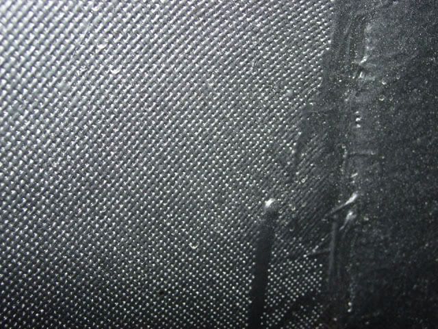
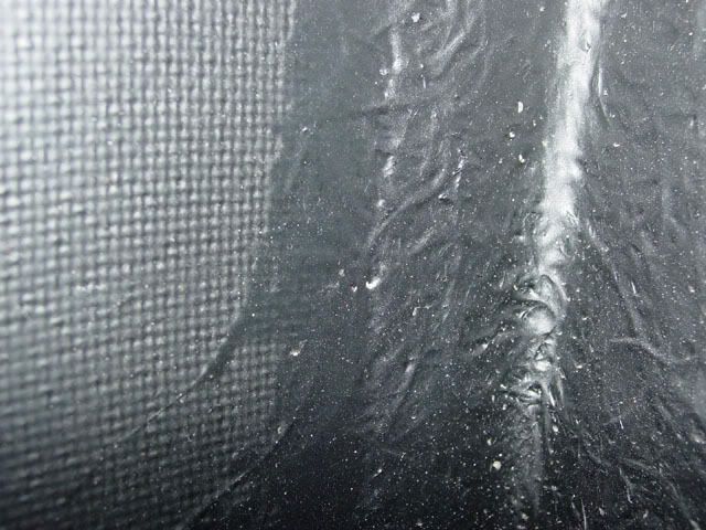
Two close-up pictures of the rear inner fender and its seam to the body. The black stuff running down is gelcoat that was painted on by the body manufacturer. It might give you some idea of how tight the weave is. The drip on the bottom picture measures .188 wide. I took a piece of the material to a local fiberglass shop and he said it was graphite fabric. A friend of mine who does a fair amount of glassing thought it was graphite also and that is why I went to the F/G shop for info in the first place. Could they be wrong... yes!
I bought the body new from the manufacture about 13 years ago. The sales brochure says "...Our vinyl ester resin is much more expensive that the industry standard - polyester . Yet the benefits of this superior resin are reduced cracking and gelcoat blistering, vastly improved strength and resistance to flexural fatigue, and reduced resin shrinkage (meaning reduced print-through) - all important considerations in an automobile body.
I just ran into this on the back of another brochure I still have. He claims they were using "thixotropic modified vinyl ester resin" and "S-glass, Aramid (Kevlar) and graphite are the primary reinforcing materials used in..." Also "Up to seven different types of reinforcing fabric, including Kevlar, graphite and high-strength S-glass are impregnated with a superior quality, moisture and vibration resistant resin to create each ..." Does anyone know what S-glass is other than http://www.azom.com/details.asp?ArticleID=769
Vinyl ester resin also allows the use of superior reinforcing fabrics - Kevlar and graphite. (While these fabrics may be used with polyester resin, polyester lacks the toughness to appreciate their strength)." Does this mean anything... no! I did run into the guy who built the body (out of the business now) and he said that the vinyl ester was what he used but could not remember what the fabric was as he had use several on the different car bodies they sold (Dauphin 2+2, Vokaro, Machette Speedster, and the Sterling GT. I think he also may have had some other bodies that they had later than when I bought).
They don't say that there is Kevlar in every body they produced but the graphite may be there based on what I have been told so far.
Lee
-
Mr Bs Bug N Buggy
- Posts: 154
- Joined: Sun Oct 07, 2007 7:34 pm


-
Ol'fogasaurus
- Posts: 17756
- Joined: Mon Nov 13, 2006 10:17 pm
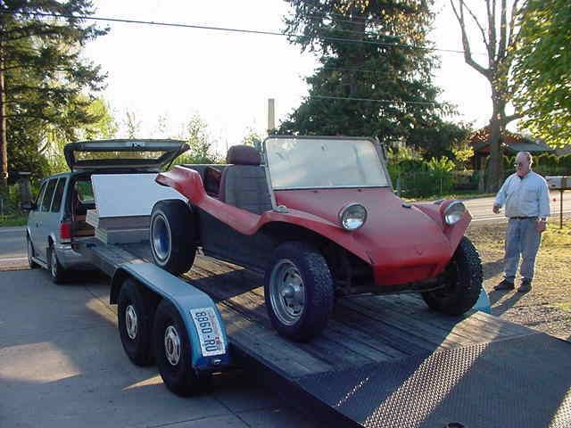
Aw, that looks so right! It has the proportions that I am trying for. I am looking at making this buggy street only. That decision having been made this week, I am going to have to get rid of the warmed over 2.8 Ford V-6 and KEP adapter kit (I am holding onto the deep bell housing 091 as a back up for my other buggy) that was going to power the buggy on the sand.
Your buggy looks like it might be a Kellison, it that right? It sits so righteous!!!! I will have to see if I can copy the pictures to a folder to use as a reference. Right now, I am just trying to fix the pan. The pan halves were so poor that it is taking a lot of work to make the fit up correct. I got the 1 X 1 X .125 wall tubing to fit in the outer channel so the body doesn’t act as the only support of the outer side of the pan. I am going to cut out the stiffening beads and use the holes to weld the pan half to the square tubing. After building the body lift, the additional support really makes a difference.
Originally I wanted a P/U like that but the longer wheel base of this body might make a better ride. That is so nice!
Lee
My opinion is worth slightly less than what you paid for it.
My opinion is worth slightly less than what you paid for it.
-
Mr Bs Bug N Buggy
- Posts: 154
- Joined: Sun Oct 07, 2007 7:34 pm
Thanks for the compliments, I am not sure if it was a kellison or not, back then I was not into buggies like I am now. I found it and it had been done as an off roader and I told my wife I could make it into a pretty cool street rod, she looked at me like this....  ......we loved that car,but sometimes life makes you do things you don't really want to do so we sold it.
It is still here in Spokane but is not being taken care of as we did, I even saw it stored outside here during the winter one year....

I have tried to buy it back but the guy won't sell it.......at least that means he likes it, so I guess that is cool.
It is still here in Spokane but is not being taken care of as we did, I even saw it stored outside here during the winter one year....
I have tried to buy it back but the guy won't sell it.......at least that means he likes it, so I guess that is cool.
-
Ol'fogasaurus
- Posts: 17756
- Joined: Mon Nov 13, 2006 10:17 pm
http://seattle.craigslist.org/oly/rvs/457503204.html
Does this give you any ideas! Sell the rotary for a good VW motor, etc.!
Does this give you any ideas! Sell the rotary for a good VW motor, etc.!
Lee
My opinion is worth slightly less than what you paid for it.
My opinion is worth slightly less than what you paid for it.
-
Mr Bs Bug N Buggy
- Posts: 154
- Joined: Sun Oct 07, 2007 7:34 pm
-
Ol'fogasaurus
- Posts: 17756
- Joined: Mon Nov 13, 2006 10:17 pm
Nice looking buggy Mr B. Good start.
I am finally giving up on the cheap pan halves. After another series of blowouts while trying to do the short welds. I am cutting out the mess I have and replacing them with the heavier gauge material pan halves. They look better and no wrinkles. The run about $175 per side (locally).
I also went to HF and got a air punch and flanging tool ($49.95). What fun! You slip the sside of the metal in, pull the trigger and a soft pfft and suddenly there is a nicely cut .190 hole. I think id will be easier to add the new pan halves by doing the rosette welds method. The tool also make great step (Zee) flanges for flat overlap sheet joining.
A great tool to have in your tool box (as long as you have air pressure available anyway).
Lee
My opinion is worth slightly less than what you paid for it.
My opinion is worth slightly less than what you paid for it.
-
Ol'fogasaurus
- Posts: 17756
- Joined: Mon Nov 13, 2006 10:17 pm
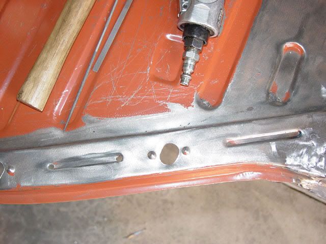
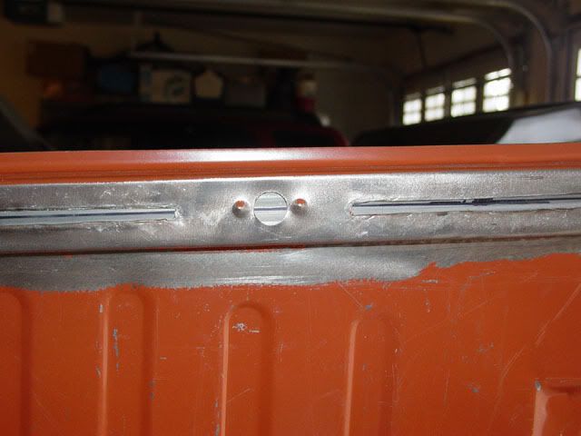
I finally got to work on the buggy today. Between taxes, fighting the flu (again) and other things I finally got the heater control slots on the pan's tunnel closed out.
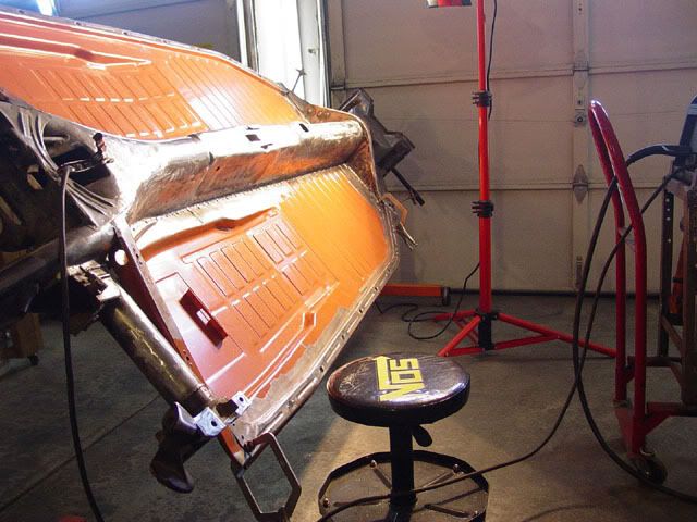
In this picture, you can see the two main holes in the tunnel. The one farthest forward it the hole for the shifter. The second one is for the emergency brake and on each side of it are the two slots for the heater controls.
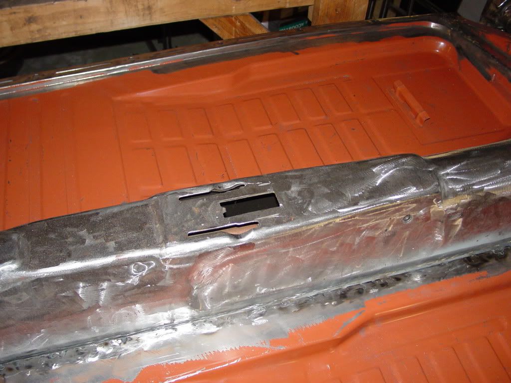
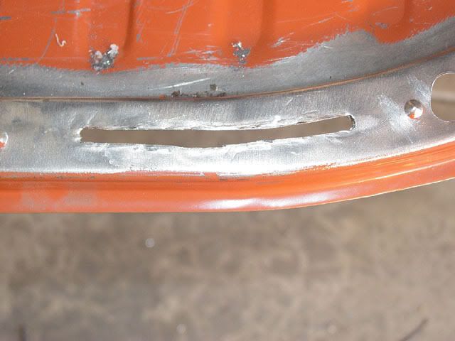
These are to two slots to be removed.
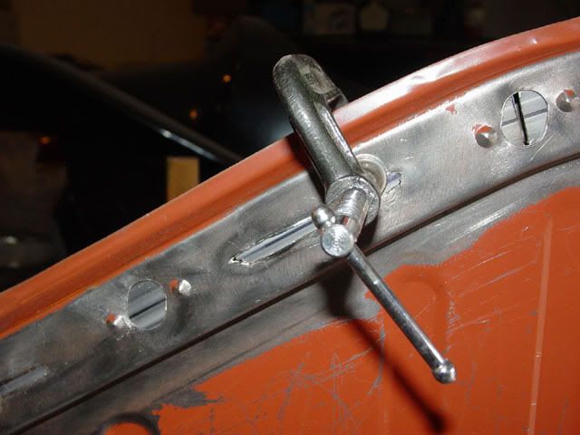
A similar picture as the first one showing the two slots being closed out. Also the new mount for the hydraulic pedal assembly.
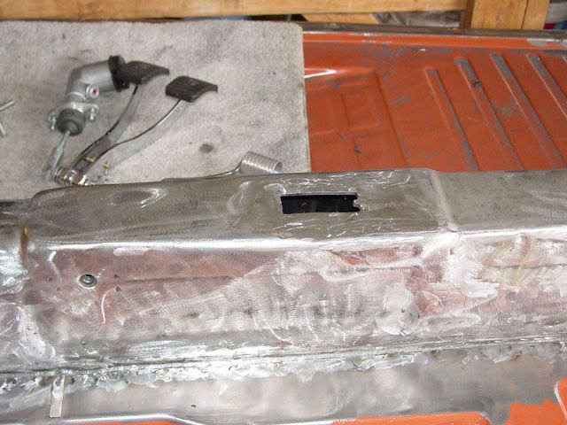
From the passenger side.
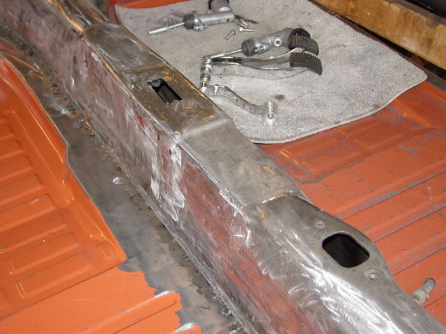
Looking towards the rear of the car from the passenger (right) side.
I have yet to decide how to handle (cover) the emergency brake hole (the one towards the rear) and the hole for the gear shifter. Part of the problem is that I want to be able to put this on the street at some time and the emergency brake hole would then be used. right now, the turning brake assembly will be sitting somewhere in the area of the e-brake.
As far as the shifter goes, since I am planning on using a bus transaxle, the nose cone of the transaxle will enter the car above the tunnel. Also, since I should (plan on) sitting a little farther back and much lower than the stock VW seats are, the shifter (especially using a straight handled after market shifter) will need to sit a little farther south than stock. I think I will shorten and make the shift rod adding in universals. I will also incorporate an adjuster to lengthen or shorten the shift rod with out having to cut it a second time. I have seen the universals done but not tried it. It look\ really clean and allows the use of the earlier stock, solid coupler and also deals with some of the shift box and transaxle miss-alignment that will be there..
I thought about either welding the holes shut and being done with it (both the e-brake and the shifter access holes) or just tacking in a fill piece over each hole. Hotrod suggested I could make a bolt on cover out of AL. I could put either engine turn finish them or if I was really inventive, I could machine some fins on the cover for cooling (yea... right!). I could modify the shifter box and the turning brake mounts to miss them so that is not a problem. It would make a good project and I should be able to learn something. I have yet to try installing riv-nits so another chance to try something new.
I still have to build a body lift for this pan.
In this picture, you can see the two main holes in the tunnel. The one farthest forward it the hole for the shifter. The second one is for the emergency brake and on each side of it are the two slots for the heater controls.
These are to two slots to be removed.
A similar picture as the first one showing the two slots being closed out. Also the new mount for the hydraulic pedal assembly.
From the passenger side.
Looking towards the rear of the car from the passenger (right) side.
I have yet to decide how to handle (cover) the emergency brake hole (the one towards the rear) and the hole for the gear shifter. Part of the problem is that I want to be able to put this on the street at some time and the emergency brake hole would then be used. right now, the turning brake assembly will be sitting somewhere in the area of the e-brake.
As far as the shifter goes, since I am planning on using a bus transaxle, the nose cone of the transaxle will enter the car above the tunnel. Also, since I should (plan on) sitting a little farther back and much lower than the stock VW seats are, the shifter (especially using a straight handled after market shifter) will need to sit a little farther south than stock. I think I will shorten and make the shift rod adding in universals. I will also incorporate an adjuster to lengthen or shorten the shift rod with out having to cut it a second time. I have seen the universals done but not tried it. It look\ really clean and allows the use of the earlier stock, solid coupler and also deals with some of the shift box and transaxle miss-alignment that will be there..
I thought about either welding the holes shut and being done with it (both the e-brake and the shifter access holes) or just tacking in a fill piece over each hole. Hotrod suggested I could make a bolt on cover out of AL. I could put either engine turn finish them or if I was really inventive, I could machine some fins on the cover for cooling (yea... right!). I could modify the shifter box and the turning brake mounts to miss them so that is not a problem. It would make a good project and I should be able to learn something. I have yet to try installing riv-nits so another chance to try something new.
I still have to build a body lift for this pan.
Lee
My opinion is worth slightly less than what you paid for it.
My opinion is worth slightly less than what you paid for it.
-
Leatherneck
- Moderator
- Posts: 17104
- Joined: Sat Jul 01, 2006 6:47 pm
-
Ol'fogasaurus
- Posts: 17756
- Joined: Mon Nov 13, 2006 10:17 pm
-
Ol'fogasaurus
- Posts: 17756
- Joined: Mon Nov 13, 2006 10:17 pm
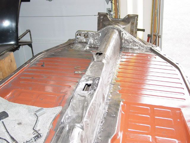
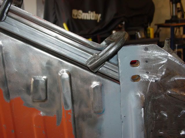
An update to the pan.
I now am working on stiffening the parimeter of the pan. With the removal of the body, especially the roof, the parimeter of the pan is really weakened. Fiberglass is not really that structural in this case so I decided to stiffen the body mount channel. I still am undecided as to off-road or street so even if I build a three inch body lift for it, if figure that the extra material I am adding will be stronger to blot to than the thin pan material.
I measured, the channel length, then purchased two 6 foot pieces (this is an unshortend pan) of 1 inch square, .125 wall tubing.
The stiffening bead protude down into the channel and would not allow the tubing to sit flat against the channel. The beading was not all that good anyway but did do some stiffening of the channel. You could easily deform the edge of the channel, especially at the large bent towards the fron of the pan.
I startd by drilling out the ends of the stiffening beads then cut the rest of the material with a cut-off tool. I did this to all nine beads.
I didn't worry about looks as this area will be rosette/plug welded to the tubing.
I started forming the tubing by taking an angle duplicator and finding the angle that the tubing will have to be cut when it sits in the channel and transferred it to the tube then cut the tube.
I also found the points of tangency of each bend in the channel and marked them. I then laid the tubing in the channel and marked the first point of tangency on the tube. Since it is awkward to run the 6 foot length of tube around the bend, I took a piece of string and laid it in the tunnel and marked both the start and end of the bend (tangency). You don't have to stretch the string, just lay it in. I then transferred the distance to the tube. From the second tangency mark, I laid the tube in the channel again and marked the first point of tangency of the second bend. I then found the length of the second point of tangency for that bend and marked it. I then found the remaining distance for the length of the tube, marked it and cut it off. Not much trim was taken.
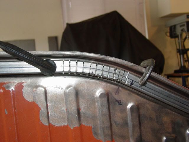
I then took a square and made a mark across the tube at each tangency point. I decied that I wanted the seam in the tube to be in the inside radius as welds don't bend well and I didn't want the bolt up against the seam either. I transferred the tangency marks to three of the sides leaving the outside of the bend alone. I also marked a center line on the top and bottom sides of the tube the full length of the tube (more on why I did this later). I then divided the area between the tangency marks into roughly i/a inch divisions. I transferred the marks to all three sides.
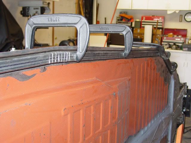
Using a cut-off tool with a 1/16 thick disc, I made kerf cuts on all three side using the marks I had made. I laid the tube in the channel and clamped it down. I had to pull it once and slightly widen the kerf cuts on the inside surface once. Once everything was roughly in place the other side looked like this.
Now you can see why the center line of the tube was added. It shows where the tube is sitting and how much adjustment has to be made. By loosening the clamps and wedging the tube some, I was able to get things in place.
A little mor adjustment and it is time for welding the kerfs up.
I have started the welding process but this is basically where I am now.
I now am working on stiffening the parimeter of the pan. With the removal of the body, especially the roof, the parimeter of the pan is really weakened. Fiberglass is not really that structural in this case so I decided to stiffen the body mount channel. I still am undecided as to off-road or street so even if I build a three inch body lift for it, if figure that the extra material I am adding will be stronger to blot to than the thin pan material.
I measured, the channel length, then purchased two 6 foot pieces (this is an unshortend pan) of 1 inch square, .125 wall tubing.
The stiffening bead protude down into the channel and would not allow the tubing to sit flat against the channel. The beading was not all that good anyway but did do some stiffening of the channel. You could easily deform the edge of the channel, especially at the large bent towards the fron of the pan.
I startd by drilling out the ends of the stiffening beads then cut the rest of the material with a cut-off tool. I did this to all nine beads.
I didn't worry about looks as this area will be rosette/plug welded to the tubing.
I started forming the tubing by taking an angle duplicator and finding the angle that the tubing will have to be cut when it sits in the channel and transferred it to the tube then cut the tube.
I also found the points of tangency of each bend in the channel and marked them. I then laid the tubing in the channel and marked the first point of tangency on the tube. Since it is awkward to run the 6 foot length of tube around the bend, I took a piece of string and laid it in the tunnel and marked both the start and end of the bend (tangency). You don't have to stretch the string, just lay it in. I then transferred the distance to the tube. From the second tangency mark, I laid the tube in the channel again and marked the first point of tangency of the second bend. I then found the length of the second point of tangency for that bend and marked it. I then found the remaining distance for the length of the tube, marked it and cut it off. Not much trim was taken.
I then took a square and made a mark across the tube at each tangency point. I decied that I wanted the seam in the tube to be in the inside radius as welds don't bend well and I didn't want the bolt up against the seam either. I transferred the tangency marks to three of the sides leaving the outside of the bend alone. I also marked a center line on the top and bottom sides of the tube the full length of the tube (more on why I did this later). I then divided the area between the tangency marks into roughly i/a inch divisions. I transferred the marks to all three sides.
Using a cut-off tool with a 1/16 thick disc, I made kerf cuts on all three side using the marks I had made. I laid the tube in the channel and clamped it down. I had to pull it once and slightly widen the kerf cuts on the inside surface once. Once everything was roughly in place the other side looked like this.
Now you can see why the center line of the tube was added. It shows where the tube is sitting and how much adjustment has to be made. By loosening the clamps and wedging the tube some, I was able to get things in place.
A little mor adjustment and it is time for welding the kerfs up.
I have started the welding process but this is basically where I am now.
Lee
My opinion is worth slightly less than what you paid for it.
My opinion is worth slightly less than what you paid for it.
-
RyanB

- Posts: 1466
- Joined: Wed Feb 26, 2003 12:01 am
Very nice Lee! Love the info. will be alot stronger now!
--------------------------------------------------------------------
My current build thread:
http://www.shoptalkforums.com/viewtopic ... 8&t=139952
R.I.P. Alfred Munson I miss you. http://www.volksrods.com/forum/showthread.php?t=9927
My current build thread:
http://www.shoptalkforums.com/viewtopic ... 8&t=139952
R.I.P. Alfred Munson I miss you. http://www.volksrods.com/forum/showthread.php?t=9927
-
Ol'fogasaurus
- Posts: 17756
- Joined: Mon Nov 13, 2006 10:17 pm
Thanks Ryan.
I forgot to mention that on the cuts for the tangent lines, I made them fat to the outside. The points for tangency for the inside radius and the outside radius of the channel are different lengths so by going fat you get a good average between the two. I also found when doing the three inch body lift, you might have to make an extra set of kerfs outside of either one or both of the tangent points on the big bend.
I hope I didn't get too basic on what I did. I intended the construction info to be helpful to people who hadn't any experience with this kind of build.
Lee
My opinion is worth slightly less than what you paid for it.
My opinion is worth slightly less than what you paid for it.