I found an excellent wiring diagram on JBugs website that showed the entire wiring diagram in color and very well done. Problem is it was for a 72 Bug. I called JBugs in Oceanside and they told me after 72 you cannot even purchase a wiring harness for the 73 model, and there has not been a decent wiring diagram published.
When I switch on the ignition the running lights and front marker lights go on. When I turn on the right turn signal the right marker light blinks. JBugs told me the lights should not go on with the key but through the rocker light switch in position 1 (running lights).
Is there a decent diagram from the fuse box on a 73 that correctly diagrams the wiring. I have enough knowledge to chase wiring with a volt/ohm meter to test for continuity, but I would like to start with a diagram showing what wires go with what lugs on the fuse panel. Thanks
Wiring Diagram for 73 Super Beetle
-
ashman40

- Posts: 92
- Joined: Fri Dec 08, 2006 8:24 am
Re: Wiring Diagram for 73 Super Beetle
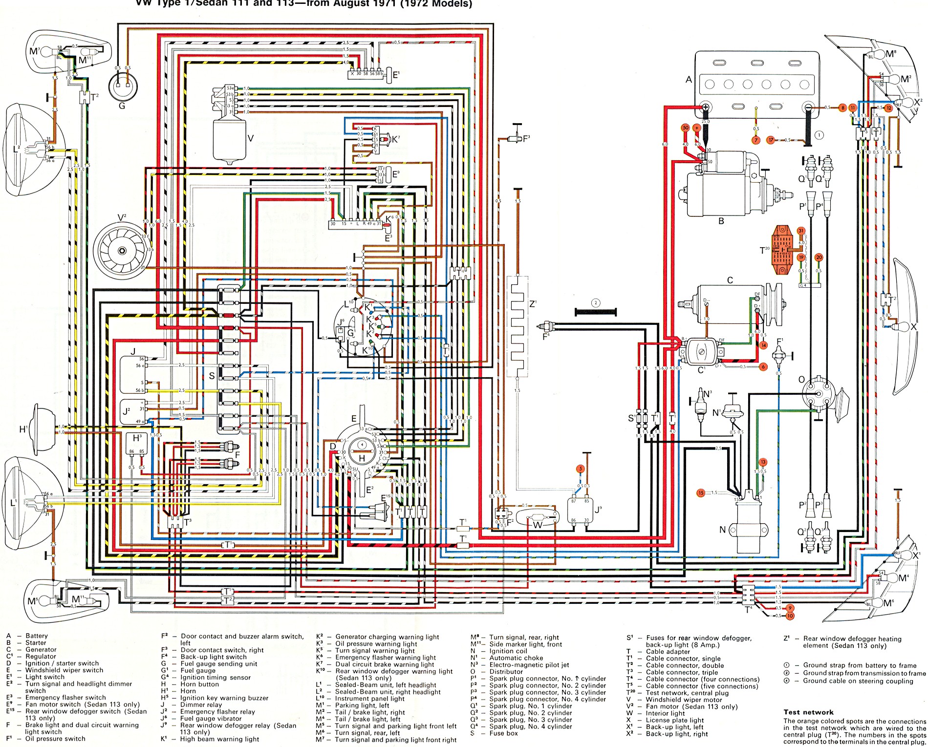
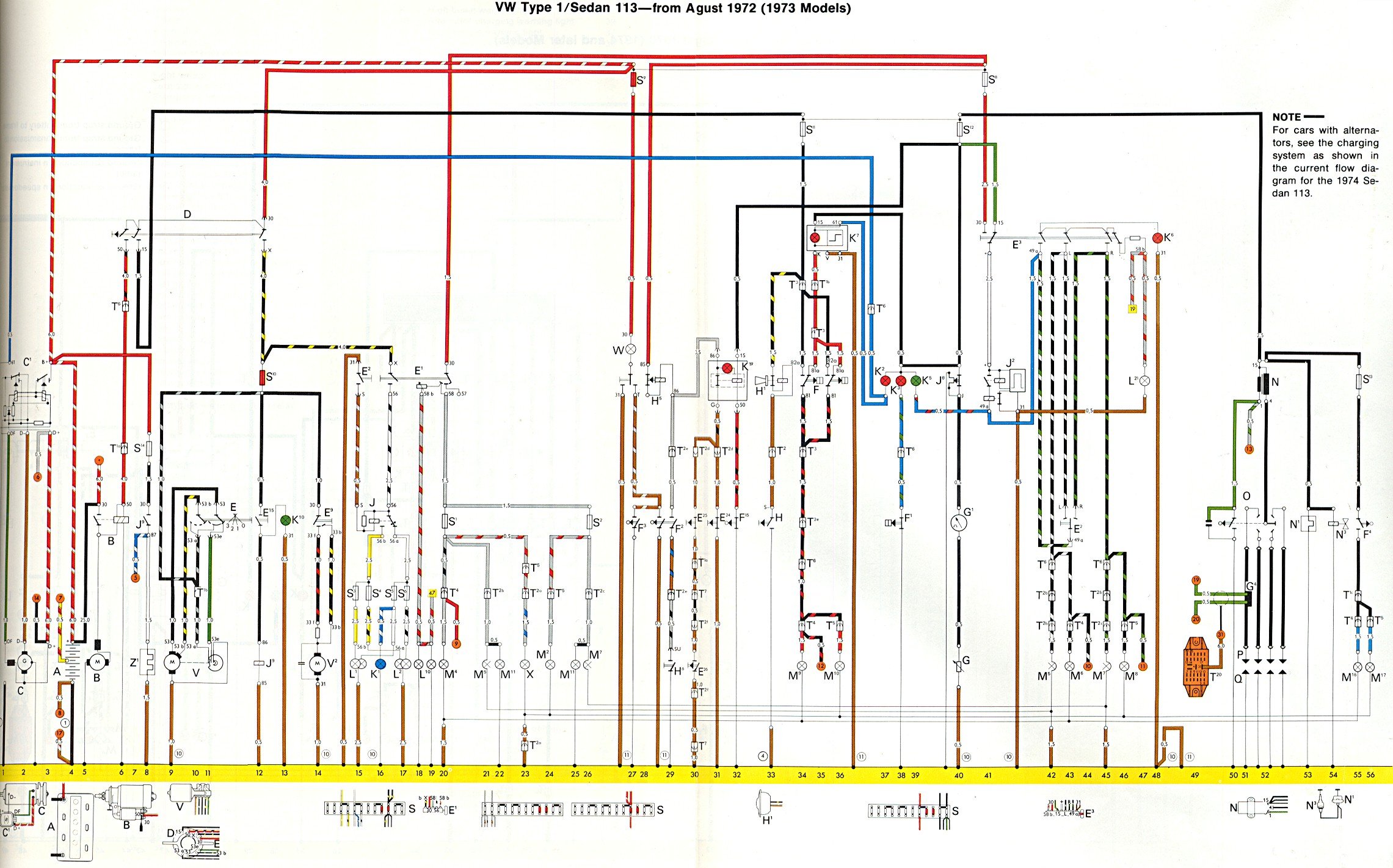
I'm not sure if your JBugs wiring diagram is the same as the one below (diagrams from theSamba.com), but '72 was the last year that VW used this type of diagram which places devices approximately where they are in the car (headlights on one end and taillights at the other) and expect you to just connect the correct color wire to the correct numbered terminal. You have no idea how the switch interconnects these different wires because you cannot see into the switch. Later diagrams don't concern themselves with proper placement but focus on the circuits and understanding the actual flow of current (you can see inside the switch and see how different wires are connected). For example, the turn signal assembly in the steering column has three circuits running thru it (turn signal, dimmer switch and horn) and those circuits appear in three different areas of the '73 diagram while in the '72 diagram all that wiring comes together at the speedometer/turn signal/horn/ignition switch cluster. If you can get used to the later diagram it is better for troubleshooting.
The difference between '72 and '73 model year wiring is small so you can use either for 95% of your wiring.
This is the early type diagram + key ('72):
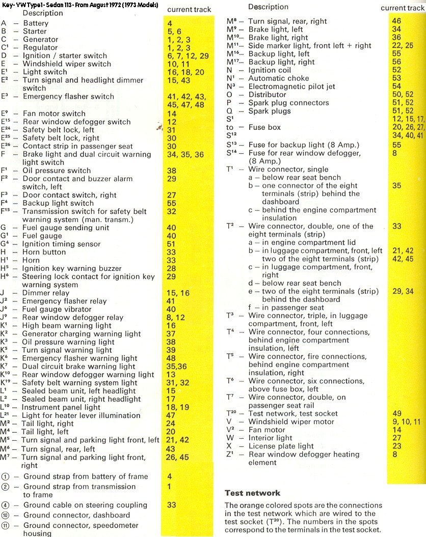
This is the later type wiring diagram ('73 SB) and the key/legend that goes with it. The positive current generally coming from the top and flows down to a common ground along the bottom of the diagram. It helps if you get familiar with where the different devices (headlight switch, wiper switch, E-Flasher switch, etc.) are located around the diagram. Use the key for this. The track#s in the key tell you which column (numbers at the bottom) the devices is located in. Note that some devices are located in multiple columns. The fuses are spread around the diagram but are numbered properly (L to R as seen from the driver's seat). This is not a problem if you work one fuse and its wiring at a time.
One key point when wiring the fuse box... there is an INPUT side to the fuse box and an OUTPUT side. While INPUT side in the diagrams may be along the top, they could be along the bottom of your physical fuse box. Looking at the '72 diagram above, the INPUT side of the fuse box is along the left side of the fuse box. You can tell by the thick black lines that connect one side of some of the fuses together. This bridge allows one wire to power two or more fuses. Look at your fuse box and you will see a brass bridge connecting pairs of fuses together. They will all be on one side of the fuse box. This is the INPUT side. The wiring to the fuses must respect this INPUT/OUTPUT arrangement. Do not connect an OUTPUT wire to the INPUT side of the fuse, or visa-versa. The wires connected to the OUTPUT side are protected by the fuses (when the fuse blows the OUTPUT side looses power). The INPUT side wires are NOT protected. This is important because there are a few circuits that are NOT fused from the factory (eg. black ignition coil wire).
TIP: The headlight fuses are ALWAYS pairs 3-4 and 5-6. This means the #3 and #4 fuses will ALWAYS be bridged together on their INPUT side. The same goes for #5 and #6. So if you look at the 3rd fuse from the end and it is not bridged (or is bridged to two other fuses), you are looking at fuse #10 and not fuse #3. This will help you confirm which fuse is #1 and which side is the INPUT side.
The difference between '72 and '73 model year wiring is small so you can use either for 95% of your wiring.
This is the early type diagram + key ('72):
This is the later type wiring diagram ('73 SB) and the key/legend that goes with it. The positive current generally coming from the top and flows down to a common ground along the bottom of the diagram. It helps if you get familiar with where the different devices (headlight switch, wiper switch, E-Flasher switch, etc.) are located around the diagram. Use the key for this. The track#s in the key tell you which column (numbers at the bottom) the devices is located in. Note that some devices are located in multiple columns. The fuses are spread around the diagram but are numbered properly (L to R as seen from the driver's seat). This is not a problem if you work one fuse and its wiring at a time.
One key point when wiring the fuse box... there is an INPUT side to the fuse box and an OUTPUT side. While INPUT side in the diagrams may be along the top, they could be along the bottom of your physical fuse box. Looking at the '72 diagram above, the INPUT side of the fuse box is along the left side of the fuse box. You can tell by the thick black lines that connect one side of some of the fuses together. This bridge allows one wire to power two or more fuses. Look at your fuse box and you will see a brass bridge connecting pairs of fuses together. They will all be on one side of the fuse box. This is the INPUT side. The wiring to the fuses must respect this INPUT/OUTPUT arrangement. Do not connect an OUTPUT wire to the INPUT side of the fuse, or visa-versa. The wires connected to the OUTPUT side are protected by the fuses (when the fuse blows the OUTPUT side looses power). The INPUT side wires are NOT protected. This is important because there are a few circuits that are NOT fused from the factory (eg. black ignition coil wire).
TIP: The headlight fuses are ALWAYS pairs 3-4 and 5-6. This means the #3 and #4 fuses will ALWAYS be bridged together on their INPUT side. The same goes for #5 and #6. So if you look at the 3rd fuse from the end and it is not bridged (or is bridged to two other fuses), you are looking at fuse #10 and not fuse #3. This will help you confirm which fuse is #1 and which side is the INPUT side.
AshMan40
---------------------------
'67 Beetle #1 (project that never made it to the road - SOLD)
'75 Beetle 1200LS (RHD) (RIP due to frame rot)
'67 Beetle #2 Project (2019 project car)
---------------------------
'67 Beetle #1 (project that never made it to the road - SOLD)
'75 Beetle 1200LS (RHD) (RIP due to frame rot)
'67 Beetle #2 Project (2019 project car)