This is a very basic rebuild of a Ball-joint from beam to be used for sand use only so some of the components (some may consider necessary for a vehicle to be used on the trails, street or hill climbing) have been removed.
The intent of the build will be to beef up the shock towers, add adjusters, use Thing trailing arms and spindles and add hook and pin travel stops. I am allowing a couple of weeks for the build but because of the onset of the official start to sand riding season, who knows, it could take longer.
As a clarification to the build; it must be said that this beam is for a glass bodied buggy which probably has more room for the stiffening flanges than a Baja or stock bodied sedan might have and that is why the stiffening flanges may be a little too wide for other vehicles which is not a problem as they can be trimmed down as needed… up to a point. This documented build is for showing how it can be done/the way I did it, but also I am sure that this is not the only way.
I first removed the pivot bracket for the stabilizer shock used to support the steering. I have not found it to be of much value on a dedicated sand vehicle but some might find it good to have. This is a personal opinion choice.
Next I remove the bracket and stop for the Pitman to bump up against. Again, it is something that I found is just in the way. On the Pitman arm, I also remove the tang that would make contact with this piece.
I had originally made some saddle mounts between the upper torsion tube and the shock towers, similar to what is on Thing (type 181 but thinking it over, but thinking it over I didn’t think it is going to do; e.g., protect what I wanted it to do so I removed it. This is where I am on the start of the build.
Tools:
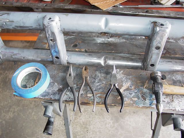
These tools, plus a piece of welding wire were what I used. I also used a grinder with a wire wheel, a horizontal/vertical band saw and a stationary belt sander with a red, heavy grit sanding belt on it.
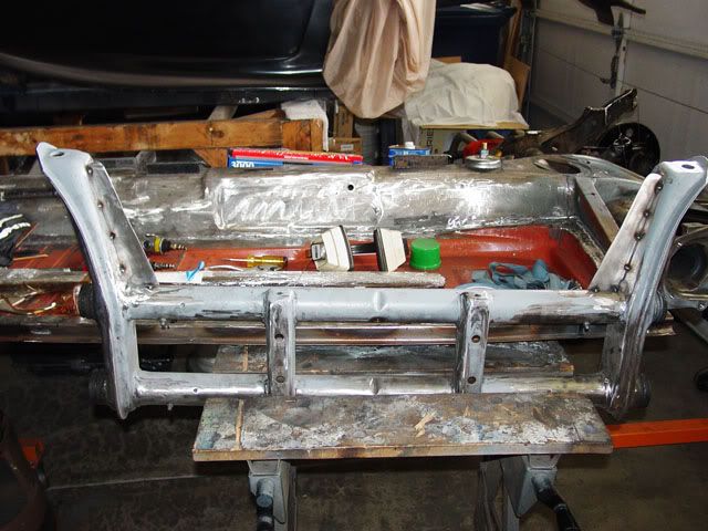
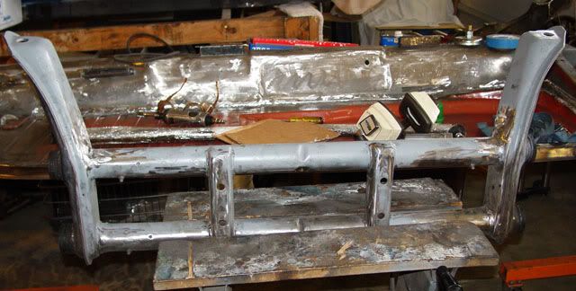
First stage, after the clean-up of unnecessary components and the removal of the spring plates.
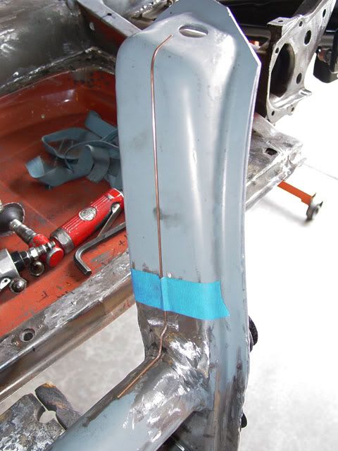
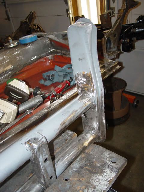
With a little patience and soft hands (meaning not being rough when bending the welding wire), I as able to pretty much form to the many contours of the join between the beam and the shock tower using both the needle nose pliers, the 90° pliers and a little finishing work using the end of the body hammer. I did have the wire break on me during the (over) manipulation of the wire and had to start over but that is all part of the game. You will find out that the face of the tower is not a straight line so you will have to use your hands to fit the bend and arc to the surface. Since I am not going to support the shock mount area because of the hook and pin stops, I do not need to bend over the top, it is there just to help support the wire frame. Also note that the shock mount area is not perpendicular to the beam but at an angle so if I was to put another strong back a little farther to the rear of the car, and was using the upper bend, it would be not in the same place but a little farther up the long piece of the frame.
I took the bent up piece of wire and traced the outline onto a piece of cardboard and then made an arbitary decision as to where to end the piece used to strengthen the shock mount. I then cut the pattern out and fit it up against the shock tower and trimmed it where needed.
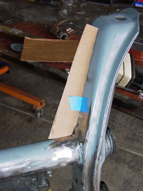
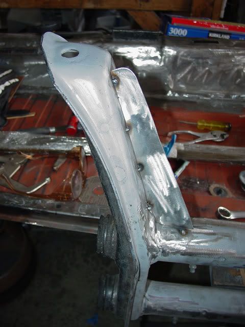
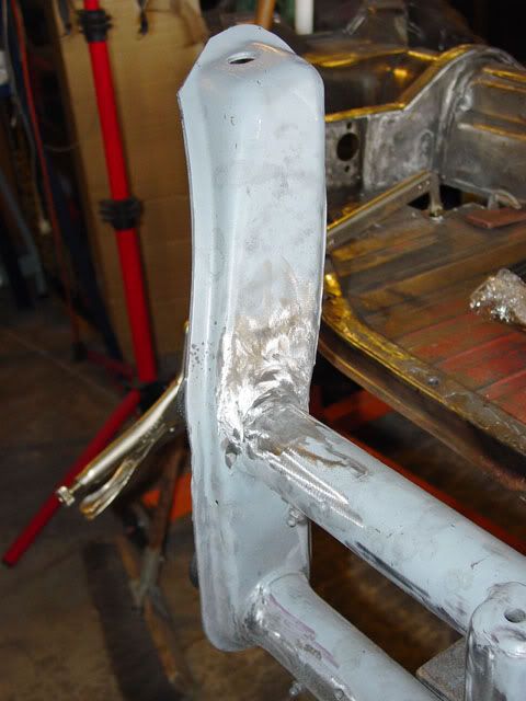
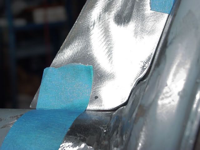
This is the final fit, not perfect but the gaps I will consider as lightening holes; actually they will be welded closed when the final part is welded in place.
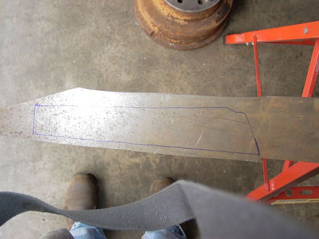
This is the shape traced onto the piece of flat stock (sorry about the shoes and strap, I was focused so much on what I was doing I missed them and did not catch it during editing). I have an old ENCO horizontal/vertical band saw and cut out the shape. They are OK as long as you have a lot of patience when the blade pops off and since the blade has a tendency to spit teeth then hook and pop off the drive pulleys you have to control you temper and not do damage to your machine (unless you are rich or have a strong arm). I don’t have a bi-metal blade on it right now so it spits teeth very easily so this is the only piece I will make until I get another blade. Several companies sell them, such as HF and Jet. Some cost more than other but you should be able to find a used one on Craig’s List but don’t spend a whole lot as they should be well under $150 if the guy is really honest.
After the basic shape was cut out, minus the step for the join between the tube and the shock mount; I deburred it using the wire wheel on the grinder then used the grinder to make the notches in the strong back. I then re-deburred it and used a belt sander with a rough grit belt to straighten the cuts up and get rid of the big burs that the grinder made. I then took a 90° grinder with a Scotch brite pad on it and cleaned the whole bracket up.
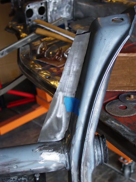
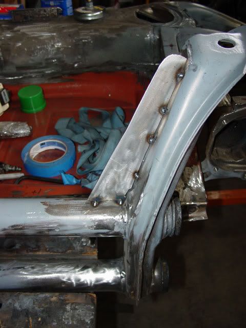
This is the final piece; the black mark on the top is where I may cut lop the end off, at least somewhere in that area anyway.
The biggest air gap which I don’t think is much. It is ready for welding in place now. As usual, the other tower is a little different but I can probably get by by tracing this one on to the flat stock and then custom trimming the lower notch some.
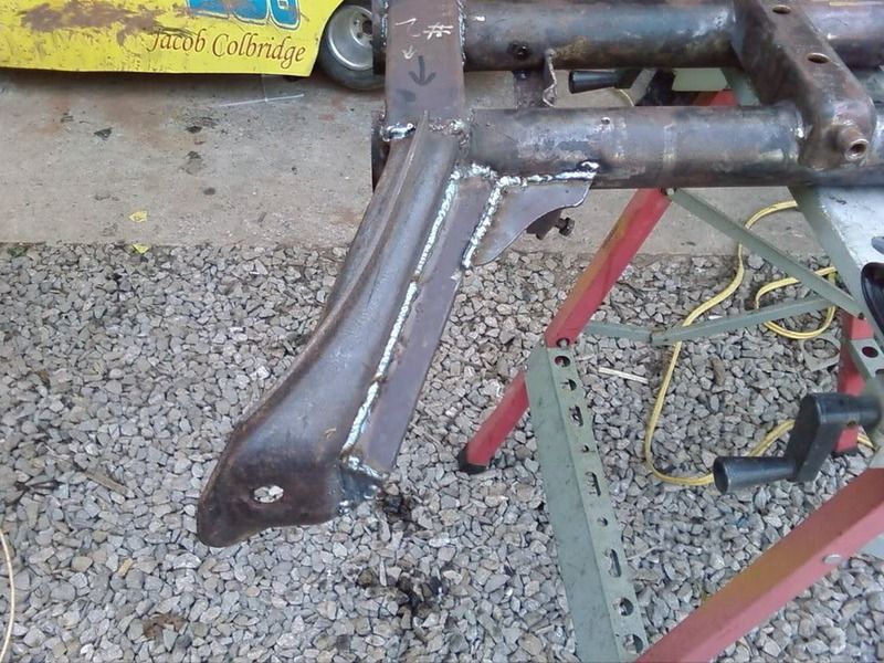
I used a little bit thinner gauge material than I would have liked to but it is about what the shock tower is, maybe a little bit heavier. It should work out for as much loading as I will put on it. Not a jumping strength though.
Lee
Edited one time to clarify some sentences. Lee
Edited a second time to delete the sentence about editing the title and also adding a new 3rd paragraph necessary to explain some things. Lee