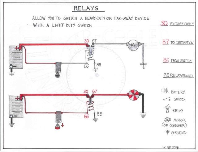
Amskeptic wrote:Relays allow you to switch heavy duty or far away devices with light duty switches.
In the case of the rear-engined VW, we get to instruct the starter to turn over the engine with a very light wire telling the starter relay to hook up the heavy duty battery cable with the equally heavy duty starter motor wire.
The convention with generic German car relay numbering is that the power supply wire is designated #30, the destination wire is #87, the instruction wire is #86, and the ground wire is #85.
In German car wiring diagrams, #30 is used not only on relays, but any time a wire is "hot". If your battery is hooked up and charged, expect full voltage at any #30 terminal you happen across. #15 is found wherever you get battery voltage when the ignition key is turned to the "on" position, that would include the #15 terminal on your ignition coil. #50 is used for any wire that receives voltage when the key is at "start."
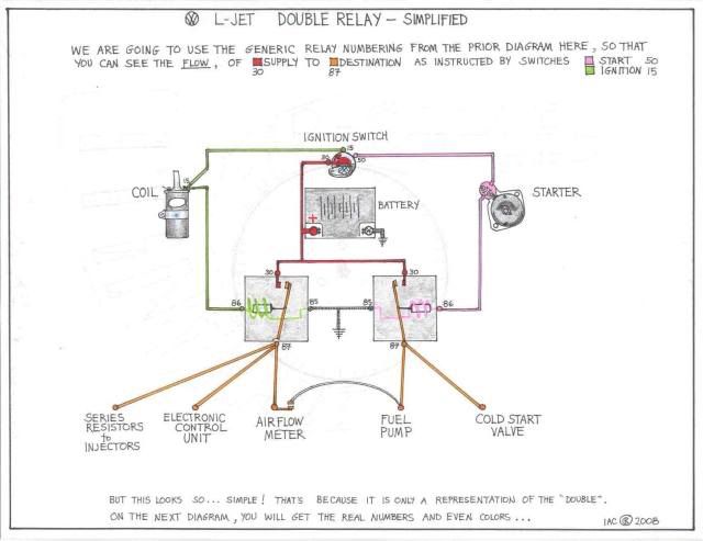
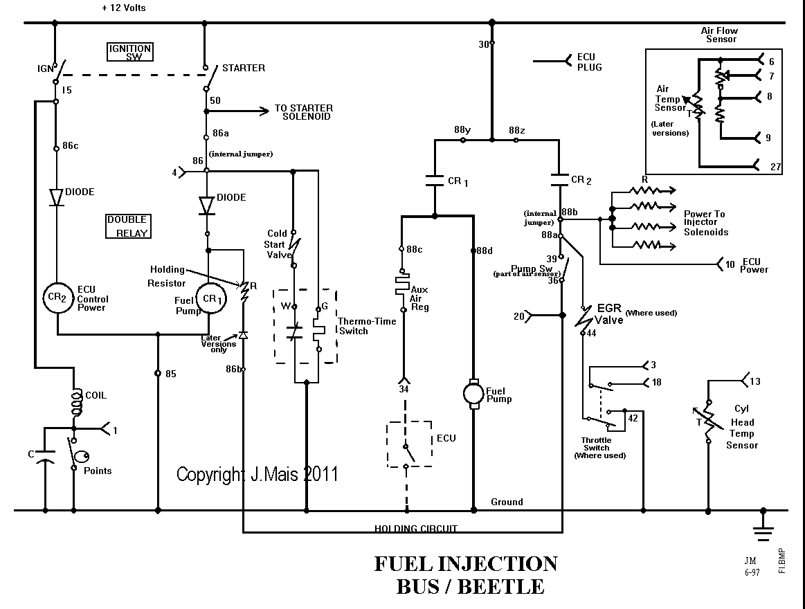
So here is our generic, simplified double relay diagram with conventional numbering just for us. All the double relay does is two things:
1) Supply voltage to the fuel injection system when the ignition is on.
2) Supply voltage to the fuel pump under two specific instructions,
a) when starting,
b) when the engine has informed the relay that it is now running under its own power.
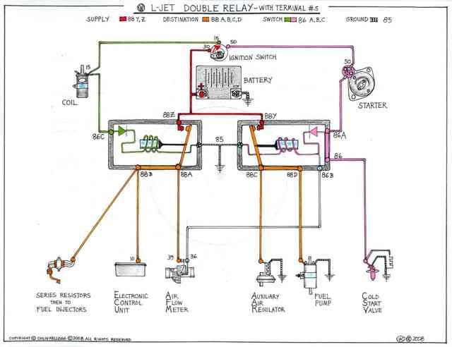
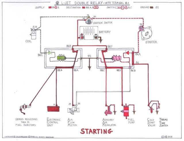
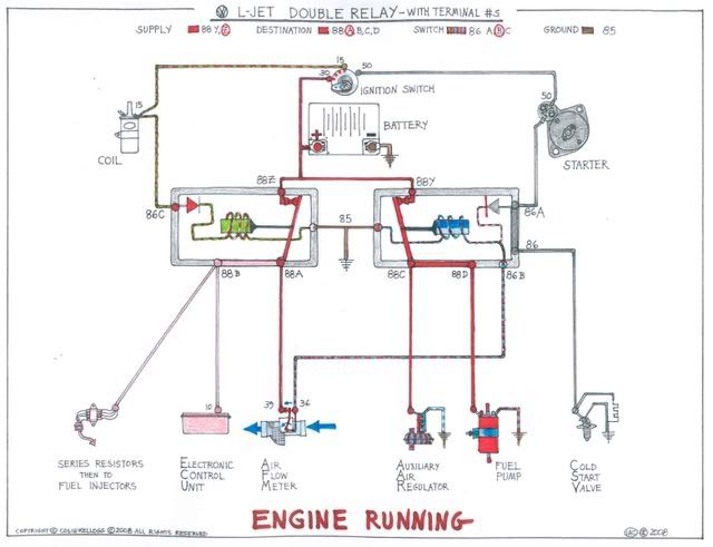
Alas, it cannot be so simple. You will also see only little adherence to the German electrical system numbering conventions at the double relay itself. But if you compare the colors used in the above generic diagram to the colors below in the actual current path diagram of your Volkswagen L-Jetronic fuel injection system, you will see the simple functions of the double relay. The ignition circuit is colored in green and it instructs the *power* relay to provide voltage to the injectors, via the voltage dropping "series resistors", and the Electronic Control Unit. The starting circuit is colored in pink. It runs the *fuel pump* relay which supplies voltage to the fuel pump, and the Auxiliary Air Regulator.
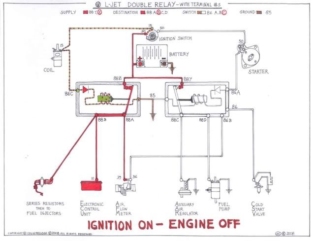
Let's run you through the sequence: First, we turn on the ignition. Power relay gets energized and the ECU and series resistors have voltage. The engine is not turning though, so we certainly don't need a fuel pump just yet.
Ignition On - Engine Off:
But, as soon as we turn the ignition key to "start" we need fuel pump and we need some cold starting assistance. (the ignition side is energized as above, but I have darkened the display to keep you focused on the starting side) With the ignition key at #50, voltage is supplied to the starter which is now turning over the engine. Voltage also continues to the double relay where the fuel pump relay is energized and connects supply voltage to the fuel pump and the Auxiliary Air Regulator (it only needs voltage to energize a timed heater). You will note (!) that there is another circuit that is energized OUTSIDE of the double relay function, the 86a > 86 terminals are "bussed" and voltage goes down to the cold start valve quite independently of anything going on inside the double relay. The cold start valve is limited to operating only when the starter #50 circuit is energized, and it shuts off when the Thermo Time Switch cuts the ground path. Like the Auxiliary Air Regulator, the Thermo Time Switch only needs voltage to energize an even faster timed heater than the AAR's.
Starting:
When the engine starts, we release the ignition key. The starter circuit drops out. The CSV and TTS are cut off as well. And inside the double relay, the fuel pump relay is going to want to drop out as well. . . . but, it doesn't. Thanks to the Air Flow Meter, which has determined that the engine is running all by itself, the power relay voltage that has been supplied to terminal #88a to the AFM all of this time, now gets to return to the fuel pump relay through 86b, illustrated with a shocking blue/red striped wire. There is a diode inside the relay that prevents the AFM voltage from running out to try to engage the starter and cold start valve, so all that happens is that the fuel pump and AAR are allowed to continue to run only so long as the AFM is reading air flow. If you stall the engine, well, consult "Ignition On - Engine Off" diagram.
Engine Running:
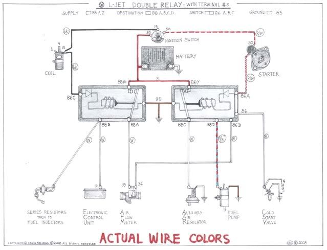
Actual wire colors and locations are unfortunately not nearly so beautiful as depicted. This might be a good thing. All wiring in the L-Jet fuel injection system is white. Vehicle wiring is color-coded.
Actual Wire Colors:
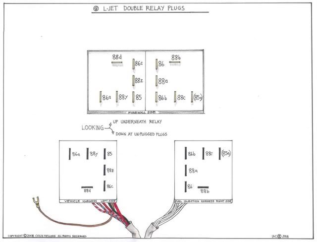
Now this is disappointing. After that nice elegant distribution of terminals in a logical way in all of the above diagrams, I have to show you the actual layout. It looks willy-nilly, but it is what VW/Bosch had to do to separate the vehicle harness from the fuel injection harness, and still get all the tracks and bus bars laid out inside the double relay. The view of the relay underside is as if you laid it on its firewall "back" side. The plugs are oriented as if you just pulled them off and stared down at them. The left plug is the vehicle harness, you can see multi-colored wires. The right plug is all white wires leading into their harness. People get confused trying to read the terminal designations on the relay and then transposing the correct terminal number onto the correct plug "slot", so here I have labelled both the double relay terminals and the plug terminals.
Note that with the correct wiring colors on the preceding diagram, you can catch that blue/red wire on the left and know instantly that it is the fuel pump supply wire coming from relay terminal #88d. From here on out, you will know that if your car refuses to start readily when cold, you can double check the red/white wire from the starter solenoid #50 terminal to make sure it is sending voltage to the double relay #86a where it buses right back out from #86 to fire up the CSV Cold Start Valve.
Enjoy. This is not terribly complicated stuff, just annoying when wires and terminals get all bunched up and you can't read designations. More to come. . .
Colin
(if your specific bus has slightly different terminal designations, do not panic. For example, the late '78-'79 buses grounded the relays internally instead of the outside wire trapped under the bracket screw. '76 buses had an electrically-controlled EGR that borrowed off the double relay. The entire series resistor pack was deleted when they discovered that they get the same voltage drop within the wires to the injectors, roll with it)
Site:
http://www.itinerant-air-cooled.com
Article in its original location:
http://www.itinerant-air-cooled.com/vie ... php?t=5459
More Info on Double Relays
- david58
- Moderator
- Posts: 14101
- Joined: Sun Oct 23, 2005 6:14 pm
More Info on Double Relays
Hot, humid air is less dense than cooler, drier air. This can allow a golf ball to fly through the air with greater ease, as there won't be as much resistance on the ball.
- david58
- Moderator
- Posts: 14101
- Joined: Sun Oct 23, 2005 6:14 pm
-
Huffy68
- Posts: 1
- Joined: Wed Feb 28, 2024 5:42 am
Re: More Info on Double Relays
Is there a relay beside the Bosch (which seems discontinued) that I can use for my 79 super beatle? I'm dead in the water.
