You do realize the welded seam on that plenum can be folded flat? I still think it might fit.
It can also be mounted with the TB on TOP, might look/work out better and saves a hair more room.
Getting the runners equal length might be an issue.
A 4>1 exhaust style collector might be neat though.
1835cc plenum advice needed -> Grelland's 1835 MS in Ghia
-
Piledriver

- Moderator
- Posts: 22776
- Joined: Sat Feb 16, 2002 12:01 am
-
grelland

- Posts: 990
- Joined: Fri May 13, 2005 2:47 am
you don't give up, do you ? 
Actually, I had a closer look myself the other night, and I will try again, as I agree this will be a lot less work than starting from scratch. I might cut the lip off, and butt-weld the seam in stead.
I do have a concern about the firewall, though, as I don't have the pan and body joined at the moment, so I cannot make accurate measurements on just how much room I have available. I hate to put a lot of effort into this, then to find out it won't fit in the car...
Thanks for reading this, though, always inspiring that others watch my progress.
Last edited by grelland on Thu Feb 22, 2007 1:12 pm, edited 1 time in total.
-
grelland
- Posts: 990
- Joined: Fri May 13, 2005 2:47 am
-
thepreacher

- Posts: 106
- Joined: Thu Aug 07, 2003 1:53 pm

-
Piledriver
- Moderator
- Posts: 22776
- Joined: Sat Feb 16, 2002 12:01 am
The 90 degree turn would be more gradual and in a smooth pipe. Actual entry is at a (hopefully) knife edged collector union, with the pulses moving straight in and out.grelland wrote:I do have an old collector lying aroud; will have a look at that idea also, but I dont see how that can be done without 90° bends on all 4 runners... Will that be a difference from the 90° turn the air will need to do wihin the plenum?
Did you understand that, btw...?
Whether it actually makes a difference is unknown, but it seems reasonable...
Addendum to Newtons first law:
zero vehicles on jackstands, square gets a fresh 090 and 1911, cabby gets a blower.
EZ3.6 Vanagon after that.(mounted, needs everything finished) then Creamsicle.
zero vehicles on jackstands, square gets a fresh 090 and 1911, cabby gets a blower.
EZ3.6 Vanagon after that.(mounted, needs everything finished) then Creamsicle.
-
Piledriver
- Moderator
- Posts: 22776
- Joined: Sat Feb 16, 2002 12:01 am
Yep.sideshow wrote:Isn't that a single IDF setup?
Point the "collector" down and put the TB underneath.
Could probably tolerate a 90 degree bend (decent radii)
Addendum to Newtons first law:
zero vehicles on jackstands, square gets a fresh 090 and 1911, cabby gets a blower.
EZ3.6 Vanagon after that.(mounted, needs everything finished) then Creamsicle.
zero vehicles on jackstands, square gets a fresh 090 and 1911, cabby gets a blower.
EZ3.6 Vanagon after that.(mounted, needs everything finished) then Creamsicle.
-
Jadewombat

- Posts: 1447
- Joined: Sat Jun 22, 2002 12:01 am
-
Piledriver
- Moderator
- Posts: 22776
- Joined: Sat Feb 16, 2002 12:01 am
Visualize bringing all 4 pipes to center, then UP, angle to match angle of front (front is front) of FH.
Put ~something like this collector and (90 degree only) elbow on it, TB goes on elbow...
By varying the length of the straight sections from either side of the 90, you could play with collector volumes/shapes. Would look cool, too
(pic is of CheekyMonkeys motor, with trimill ex)

Put ~something like this collector and (90 degree only) elbow on it, TB goes on elbow...
By varying the length of the straight sections from either side of the 90, you could play with collector volumes/shapes. Would look cool, too
(pic is of CheekyMonkeys motor, with trimill ex)
Addendum to Newtons first law:
zero vehicles on jackstands, square gets a fresh 090 and 1911, cabby gets a blower.
EZ3.6 Vanagon after that.(mounted, needs everything finished) then Creamsicle.
zero vehicles on jackstands, square gets a fresh 090 and 1911, cabby gets a blower.
EZ3.6 Vanagon after that.(mounted, needs everything finished) then Creamsicle.

-
grelland
- Posts: 990
- Joined: Fri May 13, 2005 2:47 am
Grelland's MS project
Thanks,
I should probably change the title of this thread, as this is turning more into a project thread than need for advice...
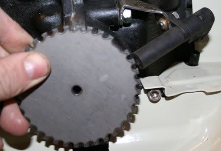
Anyways, I did get some work done yesterday; first of all some parts showed up in the mail on Saturday, and I started working on the trigger wheel setup.
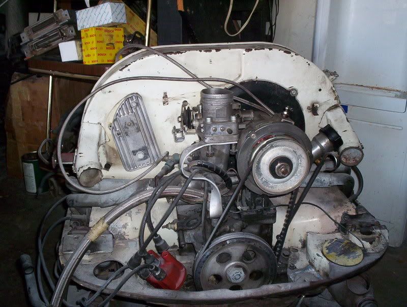
The plan is to mount the trigger wheel behind the pulley, and here is a shot of the size of the trigger wheel compared to my equalizer pulley:
There is just enough space, as far as I can tell.
The VR sensor will go on a bracket, and here I am holding it up near its correct position:
So things are moving slowly forward; next thing is to machine the trigger wheel and pulley in order to be able to bolt them together; then the bracket for the VR sensor can be permanently shaped.
I should probably change the title of this thread, as this is turning more into a project thread than need for advice...
Anyways, I did get some work done yesterday; first of all some parts showed up in the mail on Saturday, and I started working on the trigger wheel setup.
The plan is to mount the trigger wheel behind the pulley, and here is a shot of the size of the trigger wheel compared to my equalizer pulley:
There is just enough space, as far as I can tell.
The VR sensor will go on a bracket, and here I am holding it up near its correct position:
So things are moving slowly forward; next thing is to machine the trigger wheel and pulley in order to be able to bolt them together; then the bracket for the VR sensor can be permanently shaped.
-
grelland
- Posts: 990
- Joined: Fri May 13, 2005 2:47 am
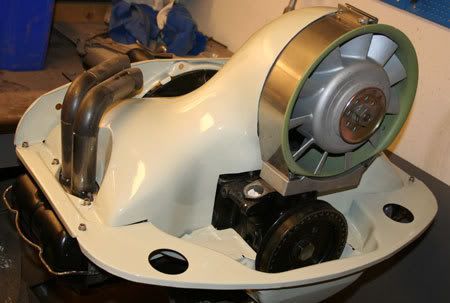
So I was able to spend another hour or so in my garage tonight, and I trial-mounted the vr sensor; the bracked may need some more refining, but here you get the idea:
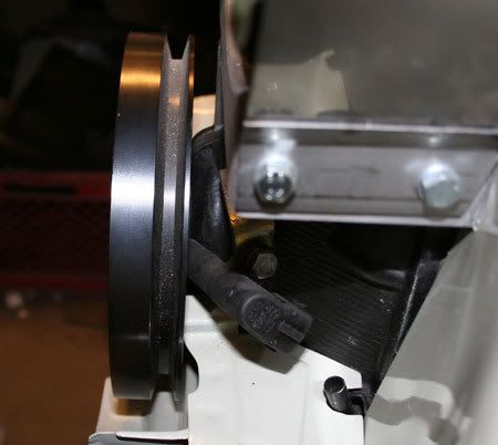
And looking from the rear of the engine, it looks like this:
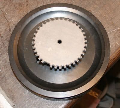
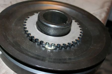
The pulley I am using have a recess in the back, perfect for placing a trigger-wheel:

I might need to grind of a small portion of the tin, as indicated here:

Now I need to get the trigger wheel machined in order to verify that everything goes together as intended, before I finish up the vr sensor bracket.
And looking from the rear of the engine, it looks like this:
The pulley I am using have a recess in the back, perfect for placing a trigger-wheel:
I might need to grind of a small portion of the tin, as indicated here:
Now I need to get the trigger wheel machined in order to verify that everything goes together as intended, before I finish up the vr sensor bracket.
-
grelland
- Posts: 990
- Joined: Fri May 13, 2005 2:47 am
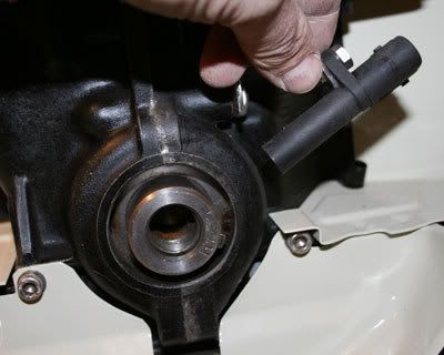
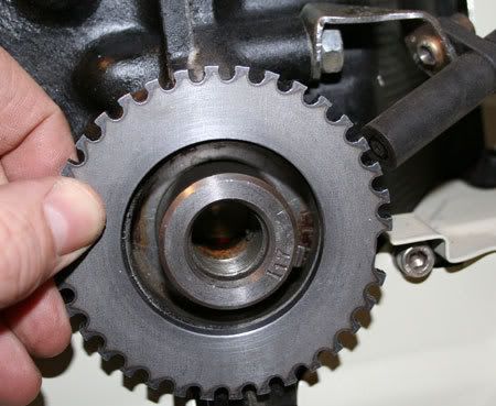
Then I had the trigger wheel machined, and this is how it all looks now:
The clearance against the case may be a challenge, but it seems to be juuuust ok:

And finally this is how I intend to mount the vr sensor:
I might end up mounting the sensor with an even steeper angle to clear the pulley better.
Roy
The clearance against the case may be a challenge, but it seems to be juuuust ok:
And finally this is how I intend to mount the vr sensor:
I might end up mounting the sensor with an even steeper angle to clear the pulley better.
Roy