After taking 30 lashes with a wet noodle from HRS about not using bluing and a scribing to do my work I moped around here for a day or two and since this string is intended to show a build, point out successes, failures and anything else the comes up so that others don't make them and since I think the instructions try to do too much in one set of instructions (K&L and BJ) which photos and some additional text might clear up some of the: 'what the..." that I decided to go back and blue the whole thing and scratch the puddin out of it with a sharp instrument assuming I can find mine or have to go purchase one that is sharp and to the point.
I went out looking for the http://www.officedepot.com/a/products/9 ... und-Ruler/ which is turning out to be quite comical. All of the people I talked to had no clue what I was talking about (not unusual in itself) but when it finally struck them what it was, a (seemed to anyway) light came on and I think they thought it was a good idea. No luck yet on finding one locally but Monday is a day I can hit up some plumbing shops but if I can't find one (I don't like to order on line) so I can always mark a piece of paper with dimension and go from there; whoo-hoo! Paper will wrap around a tube quite nicely thank you!
Since I was going to do it correct, I decided to make a welding/alignment jig (Steve talked about it) on this build as I am going to do a K&L beam after this build. For some reason I thought that the tubes slipped into the adjusters but they don’t, it is a butt fit. Well, so much for not trusting my welding ability so I’ll have to fake it and go for the gold myself. Before I go much farther on the jig I will take some pictures so you can see what I have in mind. I had allowed for some welding highs and lows in the jig but since the adjusters are roughly .05 (give or take) smaller in diameter than the beam tubes I have to make a center plate that is .02 thicker. Sometimes it is good to be lucky rather than good which today lucky appearently showed up. I’ll tell you about that tomorrow assuming I get a chance to be in the garage for any length of time (see, just on TV, they lie to you just enough to get your interest then drop you when you come and watch. Hey, I’m getting good at this!).
Lee
Basic Off-road Ball-Joint Beam rebuild PT 2 starts on p. 13
-
Ol'fogasaurus
- Posts: 17881
- Joined: Mon Nov 13, 2006 10:17 pm
-
hotrodsurplus

- Posts: 410
- Joined: Tue Sep 18, 2007 10:43 pm
Re: Very Basic Off-road Ball-Joint Beam rebuild
Well you certainly don't have to, Lee. That was just a little bit of encouragement and enlightenment to bring up the dye and scribing. I've done a fair share of layout with a marker on bare metal but it just requires more back-end work to ensure alignment.I decided to go back and blue the whole thing and scratch the puddin out of it with a sharp instrument assuming I can find mine or have to go purchase one that is sharp and to the point.
No luck yet on finding one locally
You probably aren't going to find one locally unless you work in a shipyard or hang out with pipefitters. Even then you're probably not going to get far with suppliers unless you have a union card or a business license. If you were in southern California or Las Vegas, though, you could just pop on down to Mc Fadden-Dale Industrial Hardware and order one there.
I think you're going to have to get over that. There are ways to verify security and you're not going to have a problem ordering through known places like Amazon--millions of people do it every day. It processes your payment information so the individual vendors don't ever see your vitals. But I don't think in this case that you really need that tool anyway. See below.(I don't like to order on line)
Now you're thinking in the right direction. As someone who's tried that I think you'll want to look for other material though. Paper (even chipboard) makes a terrible scribing edge. Think thinner plastics like maybe PET soda bottles. Tear one apart a two-liter bottle and cut out a 2-inch-wide strip with a straight an edge as possible. You really don't need the true templating tool unless you plan on creating angled joints. You just need a straight edge. At one shop I worked at I used the last few inches of a roll of steel shim stock for a flexible straightedge--I want to say it was .005-inch thick. But a plastic bottle wall would probably work perfectly. And you can drink the contents for an added bonus!Paper will wrap around a tube quite nicely thank you!
Okay, if your welding skills aren't up to par an overlap fit wouldn't help you anyway. Poor penetration is poor penetration whether butt, fillet, or overlap. Instead, tack each adjuster in place and take it to a proficient welder. Do one at a time and that beam will stay straight. Don't trust your well-being to a sh!t weld.For some reason I thought that the tubes slipped into the adjusters but they don’t, it is a butt fit. Well, so much for not trusting my welding ability so I’ll have to fake it and go for the gold myself.
A jig is a good idea if you're doing production work but it might be overkill in your case--I know it would be overkill in my case and I've done dozens of beams over the years. Cut and fit one adjuster at a time (you'd do it that way anyway unless you're widening/narrowing a beam) and you'll be fine. It will stay aligned. These parts aren't perfect to begin hence the adjustability.Before I go much farther on the jig I will take some pictures so you can see what I have in mind.
I had allowed for some welding highs and lows in the jig but since the adjusters are roughly .05 (give or take) smaller in diameter than the beam tubes I have to make a center plate that is .02 thicker.
Okay, now I KNOW you're overthinking this. Dead-nuts perfect radial alignment isn't make-or-break. In fact it can sit ever so slightly cockeyed without wreaking havoc. The broach in the center adjuster isn't a perfect fit anyway. That little bit of slop will let the torsion pack meet the arms properly even if the adjuster sits a little bit cockeyed.
Axial alignment is critical but only within about 1/16. Hell, I bet you could get away with 1/8 but you might as well get as close as you can.
I know from personal experience that perfect radial alignment isn't crucial. We used to narrow beams at the shop I worked at in the '90s. It was basically two horizontal lengths of 1 1/2" or so angle iron welded to two vertical spans where the beam mounting holes were (those vertical sections were drilled/tapped for the beam bolts so you could fixture the brackets). Those vertical sections were welded to two scraps of square tubing. Actually the fixture had four pieces of angle iron; the center three or so inches of each span of angle were cut away so we could weld around the backside of the beam. We held the adjusters in place as we tacked them. Held as in fingers in gloves. Nothing precision at all there. And we never heard of any alignment complaints.
As trashy and cobbled as that fixture was it was redundant for adjuster installs. We only used it when we had to narrow a beam (which was rare). Do as we did and fit one adjuster at a time and don't sweat it. The car will go down the road as straight as any stock one would.
Spend your time installing adjusters. Don't waste it on an unnecessary fixture unless you want to go into production. I want to see this car move under its own power at one point.
-
Big Dave

- Posts: 3208
- Joined: Tue May 17, 2005 4:31 pm
Re: Very Basic Off-road Ball-Joint Beam rebuild
Lee, I think you are overcomplicating this. If you make the cuts in the beam using a hose clamp, that will be straight enough. If the cuts are straight, the adjuster will be straight. Then just center the adjuster up by hand and tack it.
I don't always show my signature. But when I do, it's in this area.
-
Ol'fogasaurus
- Posts: 17881
- Joined: Mon Nov 13, 2006 10:17 pm
Re: Very Basic Off-road Ball-Joint Beam rebuild
(Sigh)
Thanks BD, that is where I was going. The jig is for a personal reason.
Lee
Thanks BD, that is where I was going. The jig is for a personal reason.
Lee
-
Ol'fogasaurus
- Posts: 17881
- Joined: Mon Nov 13, 2006 10:17 pm
Re: Very Basic Off-road Ball-Joint Beam rebuild
Without getting into all the reasons why the jig, here it is.
As usual, I had some bed frames laying around and they were straight (I think it was a Hollywood bed frame made by some company named Pat Pending or something like that)
The center piece was straight and the angle iron had wider legs than the other perimeter legs so it was the one (this kind of metal is not for cars! It may be OK for a light weight tool, stand or something like that but no bit loads in compression or side to side should be done with this stuff. The material is just not that good).
I chose to cut a length that was within the length of the beam minus the upper stiffening flange for the shock tower; I think I ended up with something like 25”s. I then cut two more pieces of the same stuff to use as a spacer; the dimensions were 10 ¾”. Because the inside radius it so tight the outer side of the radius pulled in allowing the spacer pieces to fit snug. I cleaned them in the blast cabinet, then shined the welding surfaces with a sanding disc and welded them together. When I welded the spacers in I left about 1/8” to 3/16” (eyeballed) overhang at the ends with the spacers and used this for welding. This left a gap in the center and I was able to come up with another piece from the same bed frame that was .02 wider than the spacer. This is the over-kill that was talked about. I still have to cut and weld it in.
The legs both came off the same bed and all I did was slice the sides down about an inch then figure the angle I wanted and cut away the back side of the leg at the angle I would bend the mount side at then clamped the legs in the vice and beat the crap out of them until they were at the angle I wanted.
Once I had the legs roughly where I wanted them I clamped the long angle iron to the beam and marked the outsides of the beam mounts. I then clamped the legs in centering them on the marks and welded them in place.
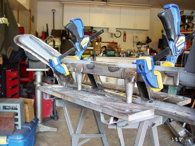
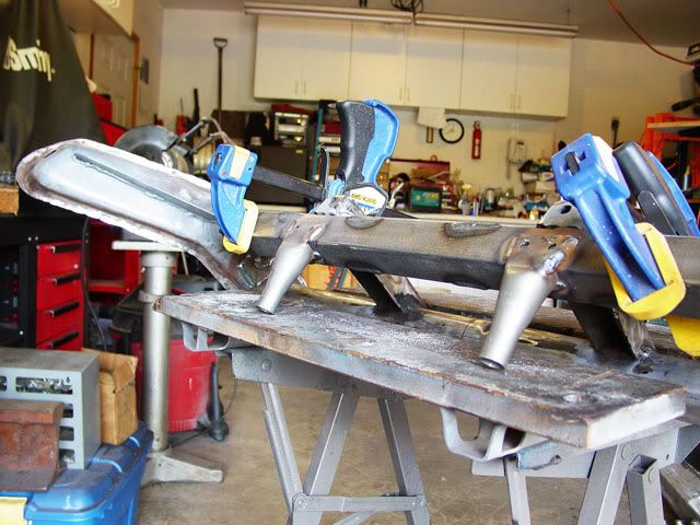
The legs aren’t perfect but they do sit flat and almost at the same angle. It if became imperative that they were equal that means must cutting two small welds and reshaping the angle of the one leg.
This tool allows me to set the angle of the beam enough to get some good tacks in place and not have to lug the beam to new positions as much.
The cost of the metal was $0 (you can find them in garage sales for almost nothing and probably cheaper at recycle centers as long as you are fast). The cost of welding wire is the big expense as well as the blast cabinet.
I’ve asked Steve if he was willing to finish off this string as he is working on one too. If not him then maybe Baja-it will do it.
Thanks for all the help guys.
Lee
As usual, I had some bed frames laying around and they were straight (I think it was a Hollywood bed frame made by some company named Pat Pending or something like that)
The center piece was straight and the angle iron had wider legs than the other perimeter legs so it was the one (this kind of metal is not for cars! It may be OK for a light weight tool, stand or something like that but no bit loads in compression or side to side should be done with this stuff. The material is just not that good).
I chose to cut a length that was within the length of the beam minus the upper stiffening flange for the shock tower; I think I ended up with something like 25”s. I then cut two more pieces of the same stuff to use as a spacer; the dimensions were 10 ¾”. Because the inside radius it so tight the outer side of the radius pulled in allowing the spacer pieces to fit snug. I cleaned them in the blast cabinet, then shined the welding surfaces with a sanding disc and welded them together. When I welded the spacers in I left about 1/8” to 3/16” (eyeballed) overhang at the ends with the spacers and used this for welding. This left a gap in the center and I was able to come up with another piece from the same bed frame that was .02 wider than the spacer. This is the over-kill that was talked about. I still have to cut and weld it in.
The legs both came off the same bed and all I did was slice the sides down about an inch then figure the angle I wanted and cut away the back side of the leg at the angle I would bend the mount side at then clamped the legs in the vice and beat the crap out of them until they were at the angle I wanted.
Once I had the legs roughly where I wanted them I clamped the long angle iron to the beam and marked the outsides of the beam mounts. I then clamped the legs in centering them on the marks and welded them in place.
The legs aren’t perfect but they do sit flat and almost at the same angle. It if became imperative that they were equal that means must cutting two small welds and reshaping the angle of the one leg.
This tool allows me to set the angle of the beam enough to get some good tacks in place and not have to lug the beam to new positions as much.
The cost of the metal was $0 (you can find them in garage sales for almost nothing and probably cheaper at recycle centers as long as you are fast). The cost of welding wire is the big expense as well as the blast cabinet.
I’ve asked Steve if he was willing to finish off this string as he is working on one too. If not him then maybe Baja-it will do it.
Thanks for all the help guys.
Lee
-
Eriksport
- Posts: 249
- Joined: Wed Sep 18, 2002 12:01 am
Re: Very Basic Off-road Ball-Joint Beam rebuild
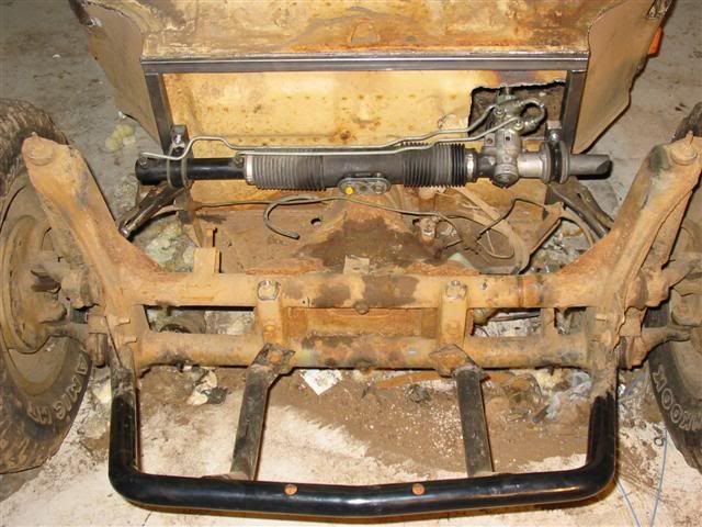
So I never really put much thought into my front beam. My car was built by hippies in Corvallis after it was hit (at least twice) in the passenger side quarter panel, most likely why it was turned into a baja. I've noticed the center has been cut/turned, and that it has small gussets down low, and angle iron stops welded much more rustic'ly than your rod/hook setup. I even had to reweld one of mine once. The seams of the shock uprights have been welded all the way around. Set the way things are, my ball joints are totally maxxed out, and somehow they still stay put. I've always kicked around the idea that when the beam dies, that I'd go A-arm. But honestly I'm kinda done hemorraging money at this car-so most likely I'll just do a Thing beam swap, or maybe still fab up my own A-arms. I have noticed that when looking straight down on the beam, my driver side lower tube is bent slightly back. Most likely due to some abusive 5' jumps from the Tuff Truck competition I entered into at the 2003 Clark County Fair.
This thread has been helpful in my Thing beam thoughts, thanks for the info thus far.
Here's what I'm working with:
This thread has been helpful in my Thing beam thoughts, thanks for the info thus far.
Here's what I'm working with:
-
Steve Arndt
- Posts: 7420
- Joined: Sat Mar 10, 2001 12:01 am
Re: Very Basic Off-road Ball-Joint Beam rebuild
Erik,
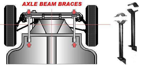
You need to build some beam support braces like what the Thing 181 had. They tie the outer ends of the beam in to the pan/frame. They are on my to do list to build. If you don't brace it the beam will bend, and it also can crack the frame head.
My digital camera is out of town. When it is back I will put up some pics of my installed beam. I also will post pics of the beam braces I'm putting together. I bought a couple pairs of the sand rail "beam clamps" like thse
http://www.pacificcustoms.com/mm5/graph ... 0770_2.jpg
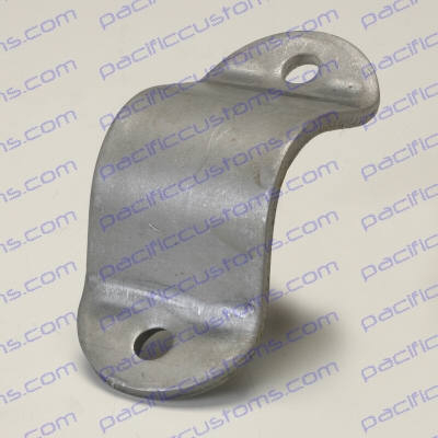
I'm going to run some tubing from those clamps towards the pan like the thing braces. Pretty much like this;
http://i258.photobucket.com/albums/hh26 ... Braces.jpg
You need to build some beam support braces like what the Thing 181 had. They tie the outer ends of the beam in to the pan/frame. They are on my to do list to build. If you don't brace it the beam will bend, and it also can crack the frame head.
My digital camera is out of town. When it is back I will put up some pics of my installed beam. I also will post pics of the beam braces I'm putting together. I bought a couple pairs of the sand rail "beam clamps" like thse
http://www.pacificcustoms.com/mm5/graph ... 0770_2.jpg
I'm going to run some tubing from those clamps towards the pan like the thing braces. Pretty much like this;
http://i258.photobucket.com/albums/hh26 ... Braces.jpg
Steve
My Baja Build
My Baja Build
-
Eriksport
- Posts: 249
- Joined: Wed Sep 18, 2002 12:01 am
Re: Very Basic Off-road Ball-Joint Beam rebuild
I have a radiator between the towers now, but I see what you're getting at. I thnk I'm going to see if if I cant get a couple horizontal ones around the pedals along the pan and tie those into the cage. Maybe even the top side too. My cage stops at the dash's plain. I will have to replace the beam before I do this, or I'd be beefing up something thats already in the wrong place. I wonder if I jump the car backwards if it'll bend it back?  hehe
hehe
-
Ol'fogasaurus
- Posts: 17881
- Joined: Mon Nov 13, 2006 10:17 pm
Re: Very Basic Off-road Ball-Joint Beam rebuild
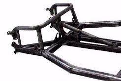
This is how Barrein and several others like Dave Barrett have approached it. the bar running from the forward hoop of the cage can connect into this which will stiffen up the front of the pan. The front or frame head join of the pan is where bending usually occurs as it is mainly un-supported when compared to the stock bodied pan. There is the frame head attached to a lower front pan and they join with the front cross-piece and tie into the tunnel and the pan itself. The bend is common with glass buggies that don’t have a roof to distribute the loads to the rest of the body and pan.
The two frame head stiffeners that Steve posted are also good especially with a steel bodied car but you may want to add some more structure to them.
If you notice, there is a cross piece between the two upper tubes and also a tube joining the lower tube at the bend. Some people also put a diagonal in from the upper front drop to the rear drop to spread some load back into the pan if the cage is not tied in.
Lee
Edit: the center bar usually is not there if there is a tunnel involved. Again, this is one of Barrien's tube chassis designs but is good to show a good way to handle things.
Lee
-
Ol'fogasaurus
- Posts: 17881
- Joined: Mon Nov 13, 2006 10:17 pm
Re: Very Basic Off-road Ball-Joint Beam rebuild
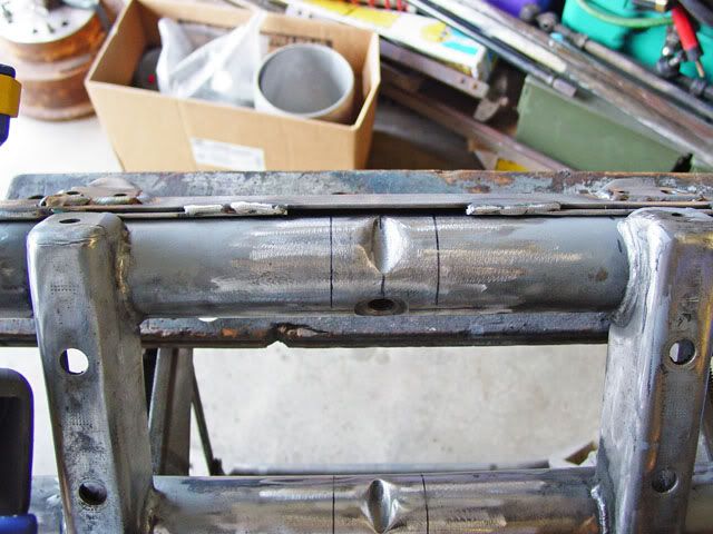
Since I couldn’t find one of those pipe measures like Hotrodsurplus was showing, I went back to my roots and made my own. The directions said that after marking a horizontal line through the grub screw hole that you make another parallel line 1 9/16 inches above it. I am assuming that they mean a long the surface so I made a template.
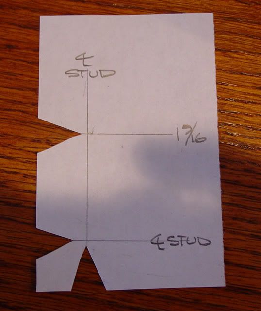
Using the old trick of marking then relieving to locate a mark I drew a horizontal line then erected a vertical line that bisected the horizontal line which indicate the centerline of the threaded stud. I then marked a point 1 9/16 above the horizontal line and drew a horizontal line, parallel to the bottom line. I then cut a Vee at each line to use to center then mark the new horizontal line.
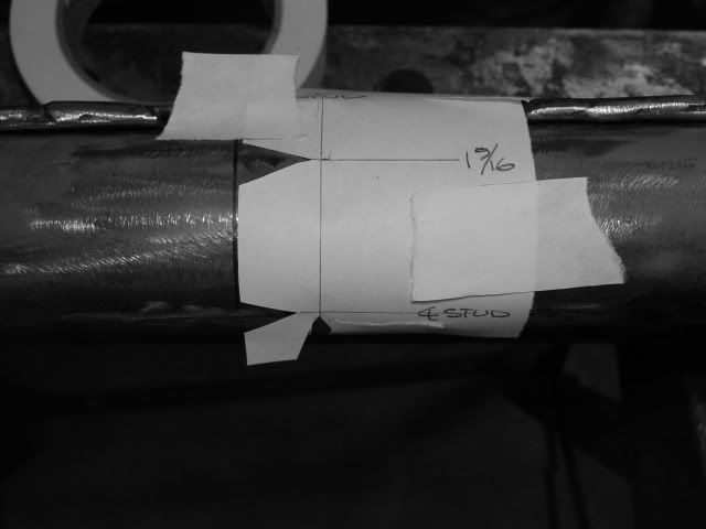
This shows the paper jig taped in place and I put a mark at the upper Vee for the new horizontal line.
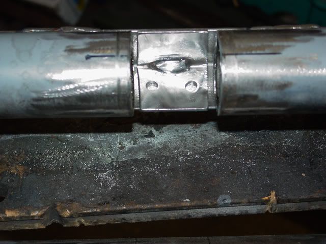
I used my grandfather’s tubing cutter but while sharp, I think the cutter is a bit worn as the cuts are a bit off line; not enough to make a difference I think but I will have to do some finish sanding and beveling.
The cutter cut all but a bit over an inch of the tube mainly because of the other tube being in the way. I finished the cut off with a cut-off tool on a pneumatic tool. It looks not too bad. The tube that the front beam is made from surprised me as to its thickness so it wasn’t just a whak, whak thank you Mack, so it took some time to do with the tubing cutter.
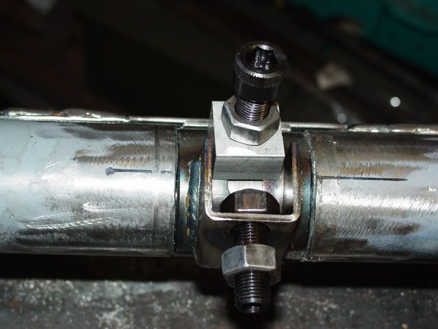
Just for giggles, I slipped the top adjuster in place to see how things fit. If I get time tomorrow I will get to making the necessary changes to the first adjuster so it can be used on a ball-joint beam. It should have pictures with it.
Lee
Using the old trick of marking then relieving to locate a mark I drew a horizontal line then erected a vertical line that bisected the horizontal line which indicate the centerline of the threaded stud. I then marked a point 1 9/16 above the horizontal line and drew a horizontal line, parallel to the bottom line. I then cut a Vee at each line to use to center then mark the new horizontal line.
This shows the paper jig taped in place and I put a mark at the upper Vee for the new horizontal line.
I used my grandfather’s tubing cutter but while sharp, I think the cutter is a bit worn as the cuts are a bit off line; not enough to make a difference I think but I will have to do some finish sanding and beveling.
The cutter cut all but a bit over an inch of the tube mainly because of the other tube being in the way. I finished the cut off with a cut-off tool on a pneumatic tool. It looks not too bad. The tube that the front beam is made from surprised me as to its thickness so it wasn’t just a whak, whak thank you Mack, so it took some time to do with the tubing cutter.
Just for giggles, I slipped the top adjuster in place to see how things fit. If I get time tomorrow I will get to making the necessary changes to the first adjuster so it can be used on a ball-joint beam. It should have pictures with it.
Lee
-
kyle_pc_75

- Posts: 1804
- Joined: Wed Jun 24, 2009 6:20 pm
Re: Very Basic Off-road Ball-Joint Beam rebuild
The title of this thread is now officially misleading. Keep it up, Lee, awesome work.
-
bajaherbie

- Posts: 9967
- Joined: Sat Jul 15, 2006 7:07 pm
Re: Very Basic Off-road Ball-Joint Beam rebuild
when i did mine, i chopped it in half with an axe, zip tied it to an old 2x4, stepped back and eye balled it with my good eye, brazed it together with a kerosene lamp and a coat hanger...... 

Of all the paths you take in life, make sure a few of them are dirt.
-
Ol'fogasaurus
- Posts: 17881
- Joined: Mon Nov 13, 2006 10:17 pm
Re: Very Basic Off-road Ball-Joint Beam rebuild
Sorry, no metal coat hangers... all plastic now days. The only metal hanger I have now has my Zoot suit on it; you know, the one with the reet pleat and and the legs taper down to 13" cuffs!
 Lee
Lee
-
Steve Arndt
- Posts: 7420
- Joined: Sat Mar 10, 2001 12:01 am
-
Ol'fogasaurus
- Posts: 17881
- Joined: Mon Nov 13, 2006 10:17 pm