Page 2 of 24
Re: Very Basic Off-road Ball-Joint Beam rebuild
Posted: Mon Jun 13, 2011 6:56 pm
by Steve Arndt
Sorry for jumping the gun in your thread. All in the name of completeness

Re: Very Basic Off-road Ball-Joint Beam rebuild
Posted: Mon Jun 13, 2011 8:43 pm
by Ol'fogasaurus
Not a problem, I actually had not thought about documenting it which I should have. Please keep me honest and thanks again.
Lee
Re: Very Basic Off-road Ball-Joint Beam rebuild
Posted: Mon Jun 13, 2011 10:51 pm
by pickstock
Steve Arndt wrote:It is important to seam weld the two halves of the stamped shock towered as well.
If you have a tig welder you can fuse the stamped pieces together without adding any filler rod. It looks almost factory that way.
i didnt think of that, it would you really nice too
thanks for posting this lee, ive seen a few before and after things jeffs book with the cut and turn and stuff but never somthing as in depth as this one, really gonna help when i end up with that damn standard
Re: Very Basic Off-road Ball-Joint Beam rebuild
Posted: Wed Jun 15, 2011 8:14 am
by Ol'fogasaurus
Off to the dunes for over a week so the next thing will be ball-joint installation followed by hook and pin installation. Sorry I didn't get the ball-joints done but I ran out of time, too much going on the last few days.
Lee
Re: Very Basic Off-road Ball-Joint Beam rebuild
Posted: Mon Jul 04, 2011 11:04 am
by Ol'fogasaurus
Well I have fooled around enough and so now it is time I got back to the beam rebuild. Remember, this is a basic build with some additions so it is time to inspect the beam.
After cleaning the area for the pins in the hook and pin stops system, I washed the area down using a degreaser, this time being lacquer thinner. Then using a angle die grinder, I put on an old brown “Scotch Brite” disc and cleaned and cleaned the area or paint and other nasties then re-wiped the area with the solvent. And inspected what I have. I also tapped on the metal of the shock mount between the beams to hear the condition of the metal. It seems to be OK so I am not wasting time with something that is beyond repair.
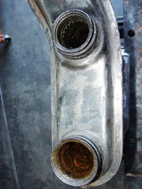
I also inspected the seals and found them to be dried out and cracked to back to the parts house after the fourth for new seals. I will show the removal in installation as soon as I can.
As you can see, the lower seal has been in bad shape for a while so the needle bearings have nasty stuff on them which I will have to clean up before going too much farther. It was a good time to do this for sure.
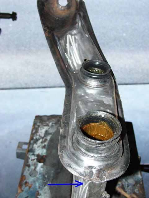
Since this beam had been on my buggy before, I decided to check the drain passage and as I thought, it was plugged closed, Using a short, thin screw driver I started worrying out the packed sand and other crap that was in there. Every ten or fifteen seconds I blew it out with compressed air (keep you face and eyes out of the way and wear eye protection.

There is another vent hole above the upper beam you can use to blow things out. Works great but a lot of stuff comes out so be careful.
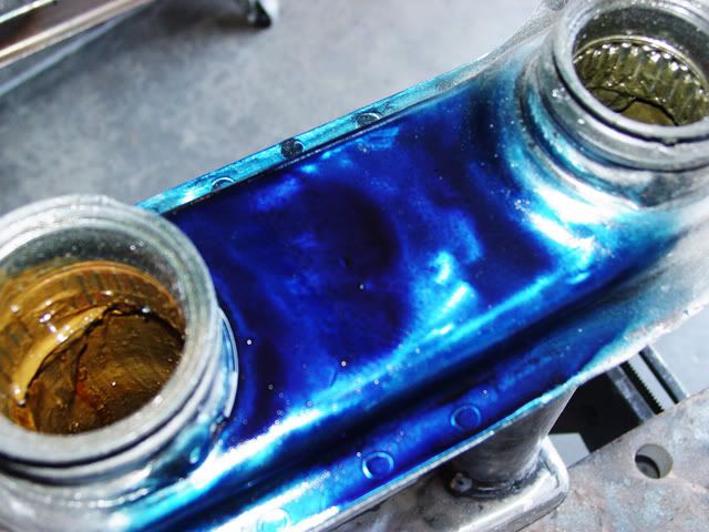
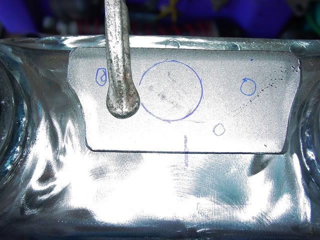
I like to use Machinist’s bluing to make my marks on metal. I am waiting for that to dry right now.
When cleaning the area I also checked the edges/seams between the two shock mount sides for seam welding in the future. There is going to be some more prep work before that but basically they looked pretty good.
Lee
Re: Very Basic Off-road Ball-Joint Beam rebuild
Posted: Mon Jul 04, 2011 1:34 pm
by Ol'fogasaurus
Back again with some updates.
I opened up the BUGPACK #6525-10 and my goodness, they had instructions in the package; Whoo-hoo! They call the kit a hook stop kit and there is a note that; “This item should be installed by qualified personnel only.” Well you know guys and that they do not look at instructions and take seemingly good advice so off we go.
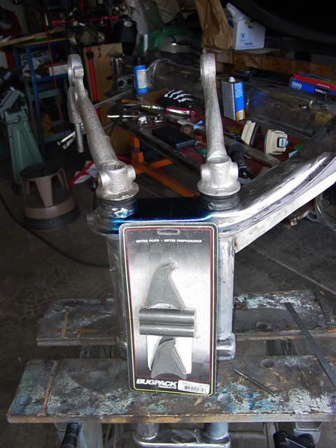
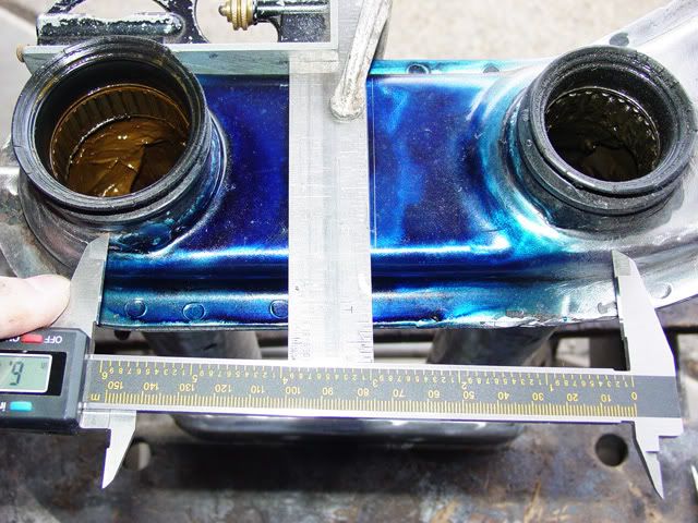
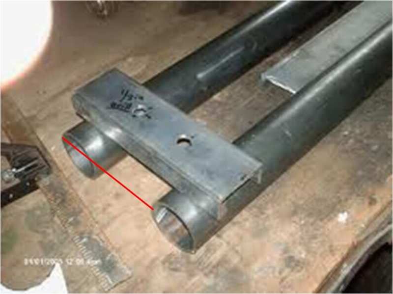
The intuitive part is that they 7/8 X 3 ¼ rod is centered between the two beams (a little over 6” between centers as best as I could measure. The picture is how I figured the centers). Their instructions assume that you pulled the trailing arms with the ball-joints and spindles still installed; I am not that lucky… yet. Because I am new to this (and dragging you along with me in my learning curve) I did a few things different. I do not trust my welding ability so I will tack and have the welding done by someone who knows what they are doing.
Instructions #1 thru #3 are detailed and take you to where we are now, instruction #4. will be done later after the rod stop is in place and then I can tack the hooks to the trailing arms in the proper locations as soon as the ball-joints are installed and I can cycle the suspension to find their proper locations, then I will have someone finish weld the rods and the hooks (my choice on this step) in place.
“#5. Rod stop should be located an equal distance between the upper and lower trailing arms and forward about 12.5 inches (??? The shock tower is only about 3” wide and the dimension is probably closer to ½ inch). They then tell you “to find the exact location hold the hook stops onto the trailing arms so that they both contact the rod stop at the same time.” Impossible with the beam still on the car; I have mine sitting on a bench with the opposite side I am working on hanging down below me. The post can be set upright there and measurements can be had if you tack the hooks onto the trailing arms and cycle the arms to locate the rod stop.
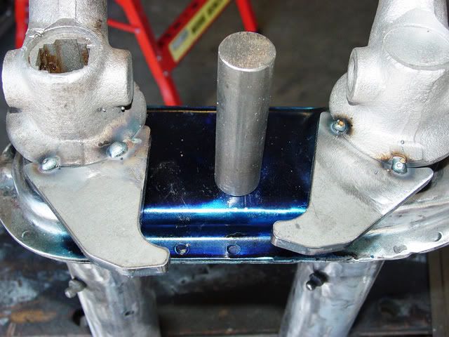
In this case, I used an arbitrary location on each trailing arm to locate the hooks on the rims of the trailing arms making sure than they are above the inner radius and away from the grease seals.
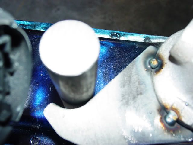
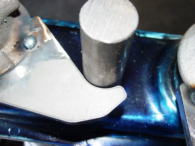
This is the best I could come up with without reshaping the arms some which I will now do. I could move the rod (I prefer to call it a post so if you don’t mind, when I write I will use the work post) a little closer to the radius of the shock mount tower but I am also leery of getting too close to the radius too. Once I have chosen a location for the post the instructions say: “#6. Scribe a circle around the rod stop on the beam.” (shock mount tower - my edit)
“#7. At the center of the circle, use a hole saw to cu a hole though both the outside and the inside of the beam (shock mount tower) support.”
“#8. Tack weld into place.” (I hope they mean the post as that is what I plan on doing.) Now you are ready to install the hook stops.”
I’m going to end this here and leave you up in the air as to whether out hero (that’s embarrassing to write but fun too) gets it done and gets it done right.
Lee
Re: Very Basic Off-road Ball-Joint Beam rebuild
Posted: Mon Jul 04, 2011 1:52 pm
by david58
Finding the true center is easy to do like this. Measure from the inner edge to inner edge like in the diagram.
Re: Very Basic Off-road Ball-Joint Beam rebuild
Posted: Mon Jul 04, 2011 2:29 pm
by Ol'fogasaurus
Thanks David, that is one way to measure it and be very accurate but it wasn't possible in this case with the seals still in place and only a 6” caliper. There are other ways to do it also but they become cumbersome with the entire math needed. I used the point of tangency method and feel I got pretty close but in actuality: I really need a 12" calipers for this and many other things too. I almost bought a 36” caliper not too long ago but did not have a good place to store and protect it even though it had a case.
After all was said and done, I was only about a 1/16th” off with the method I used and no matter what kind of corrections I made: the tolerance of the rim of the trailing arm castings (that the hooks fit to) and the hooks themselves ended up making it a best fit and a trim the rest to fit job.
Lee
Re: Very Basic Off-road Ball-Joint Beam rebuild
Posted: Tue Jul 05, 2011 10:55 am
by BAJA-IT
Lee,
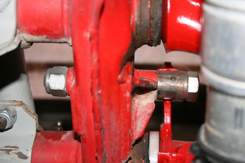
The thing I like to do when putting 'hook and rod' stops on a ball joint beam is to strengthen the tower between the beams where the rod goes through with some 1/8 inch flat strap. You can see it on both sides in this pic.
Re: Very Basic Off-road Ball-Joint Beam rebuild
Posted: Tue Jul 05, 2011 11:22 am
by Ol'fogasaurus
I agree with you BAJA-IT, the thinness of the metal of the shock mount is not the strongest even when you have two layers of formed flat stock; adding doublers and gussets are a good idea especially if you are riding hard. I kept a copy of your post the last time I brought it up and am using it for reverence (if you have the URL for your post on this, I would like to add it) to see if I am heading in the right direction. As I remember, you showed the finished product (at least as a re0ply to one of my posts), I am trying to "how to get there" type of post for anyone else trying to do this from scratch. Please keep on adding or correcting, I want this to be right.
There are some other things I want to do later that I saw in your Pix (by-the-way, I somehow lost your pictures that I mentioned above. I had a computer crash and it and some other things disappeared.
Lee
Re: Very Basic Off-road Ball-Joint Beam rebuild
Posted: Tue Jul 05, 2011 12:13 pm
by BAJA-IT
All the pix are on my Photobucket account.
Re: Very Basic Off-road Ball-Joint Beam rebuild
Posted: Thu Jul 21, 2011 3:49 pm
by Ol'fogasaurus
BAJA-IT, do you remember what size of material you used on the doublers for the stop. I am having a heck of a time coming up with a hole saw, step drill or regular drill for a 7/8 piece of round stock. I finally found someone who was willing to order a drill for me. The hole saw size of 7/8" was only in a kit of several hole saws, all of which (except for the 7/8 were odd sizes for automotive. I also like your gussets and I am pretty sure I will do the same thing or at least something similar.
After playing with the Bug Pac kit, I think your design for the post is a much better way to go. I will make a pattern of the hooks and save it for future use. They are not really a hard thing to develop once you really get into it and start to see how it was approached by Bug Pack and yours.
One of the things you did was to put a nice fitting circular cap over the hook to fit the stud; very nice but I am thinking on welding a doubler to each side of the hook instead, just to take some of the load/wear off the single thickness of the hook. Hopefully it is not needed, but just in case.
Lee
Re: Very Basic Off-road Ball-Joint Beam rebuild
Posted: Sat Jul 23, 2011 6:19 pm
by Ol'fogasaurus
I got to work on the beam some today. My 7/8” drill bit came in this morning so I felt obligated to do something even though the rain had stopped for a while and it was sunny out. The more I thought about it, BAJA-IT’s idea of a doubler where the post will sit made more sense so I started with making a doubler for that.
I plan to put doublers on both sides of the shock mount. I had some 14 ga scraps lying around so I put them in the blast cabinet and got all the bluing, crap and corruption that was on the best piece I could find and started in building the two outside pieces. I have one of those inexpensive horizontal/vertical band saws that drive people crazy and used it to cut the stock to length.
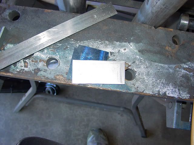
This is what I ended up with, two pieces ~3 5/16 X ~1 ½ X 14 ga. The length was what I could come up with from what I had and the width was about the same thing. I wanted enough material so I could add a couple of gussets like BAJA-IT has in the direction of the load. I have some thicker flat stock for the other side as it will need to be treated the same but in the opposite direction.
I also had to do some fitting as I wanted as much working area as I could get. This was just a matter of fitting and trimming on a grinder and de-burring on a wire wheel as I went along. I also have one of those 36 X 4 belt sanders that I use to do some fine work. I aligned the front of the doubler like BAJA-IT did allowing for some extra length for welding which is a good idea, you need a lot of edge margin here.
I then cleaned up the bluing that I had previously used with a brown scotch brite disc on an angle grinder… works very well and does not take off too much metal. I turned the ends of the post in my lathe as they weren’t square then placed the post back on the beam with the doubler clamped in place. I then put the trailing arms back in place and found the best place for the post again and marked the location on the doubler. I also made a locating tick on both the doubler and the shock mount to make sure things were OK.
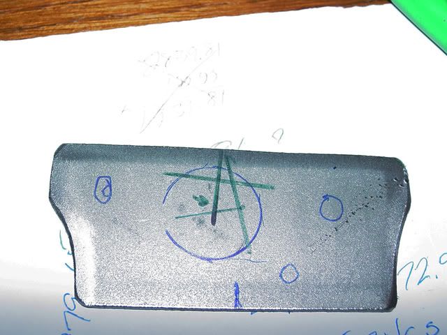
If you haven’t figured it out yet, I can be kind of anal about some things and holes are one of them. I took the doubler inside and with the help of a couple of triangles and a T. Alternater & sons (fancy and expensive ruler) scale I still have from when I did some work, and with some 4th grade (or is it 3rd grade) geometry found the center of the hole for the post and marked it. I also marked a couple of spots for some plug welds for some additional support as BAJA-IT’s doublers were thicker than the material I am using (I hope he knows what he is doing ;^))
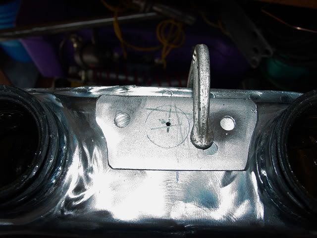
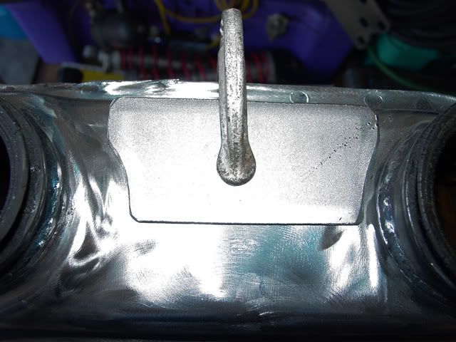
I took the doubler to the drill press where I drilled a pilot hole for the post, then took it over to the beam and located it using the ticks, placed the post on top and the trailing arms back in double checking things and then clamped it in place and drilled the pilot hole though the shock mount. I took the doubler back over to the drill press and drilled the holes for the plug welds then put the doubler back on the shock mount using the pilot drill bit to locate things back in place and aligning the two holes perpendicular proceeded to weld the doubler in place.
I had somehow hit the wire feed know and the wire was at full gallop so I have some cleanup to do and a couple of spots where moisture could collect that need to be fixed but it is basically in place (sorry, no pix as the battery in my camera was dead)
Lee
Re: Very Basic Off-road Ball-Joint Beam rebuild
Posted: Wed Jul 27, 2011 12:42 pm
by BAJA-IT
I belive I just used some 1/8" flat strap that I had laying around for the doubler.
The post on mine is 7/8"x.120 tube with a 5/8" grade 8 bolt through it. The outer piece comes off with the bolt and makes it easier to get the lower arm on the torsion springs (the hook doesn't hit the post before the springs are in the arm).
Re: Very Basic Off-road Ball-Joint Beam rebuild
Posted: Wed Jul 27, 2011 4:14 pm
by fusername
BAJA-IT wrote:I belive I just used some 1/8" flat strap that I had laying around for the doubler.
The post on mine is 7/8"x.120 tube with a 5/8" grade 8 bolt through it. The outer piece comes off with the bolt and makes it easier to get the lower arm on the torsion springs (the hook doesn't hit the post before the springs are in the arm).
i can imagine the removeable bolt saves a lot of headache. bay window bussess use bump stops on the beam, so when you get the upper arm on, you must preload that side and then go do the other, which casues the spring pack to spread and be quite annoying to assemble.