On the last installment (good lord, it was only yesterday not weeks and month like before) I had cut a 2” section out of the middle of the upper torsion tube of the brutalized stock beam.
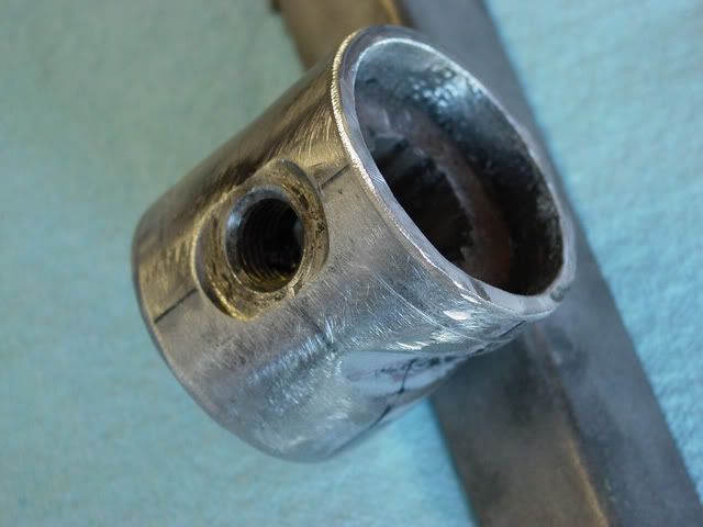
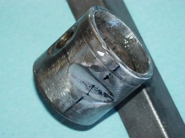
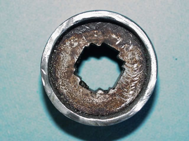
These three photos are what the offensive section of the torsion tube looks like just in case anyone wonders. I found it fascinating in a destructive sort of way.
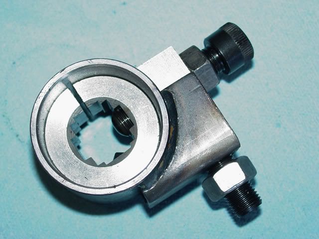
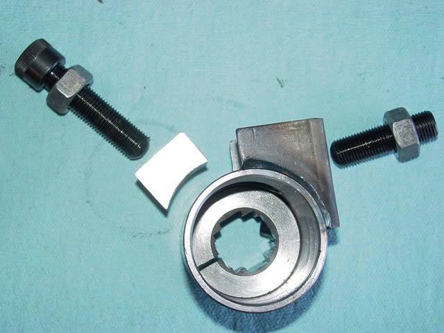
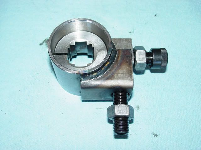
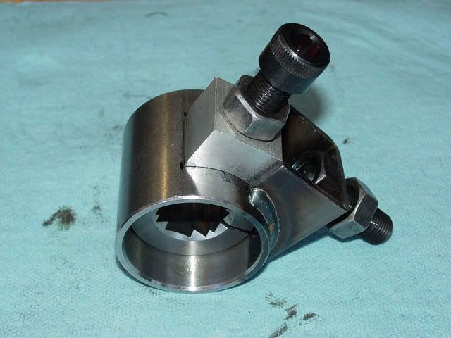
This is what the adjuster looks like coming off the card. Pretty little thing that breaks down as follows:
This is the outside portion of the adjuster exposed and…
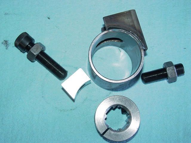
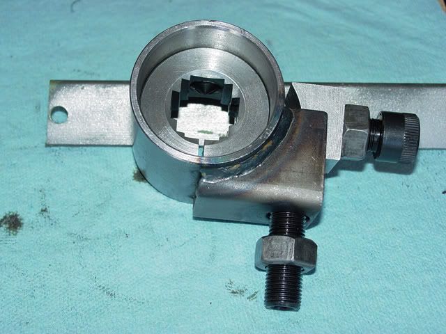
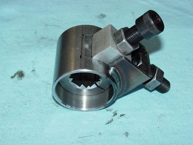
This is the center piece removed for some changes to be made.
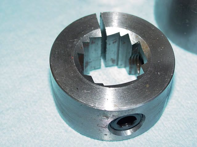
There are two threaded holes in the center section, one is filled with a threaded plug and the other one is where the adjuster threads into. Using a 6mm Allen Wrench you remove the plug from one hole and move it to the other hole. The top must be flush with the top of the center section so that the center section will slide into the body of the adjuster.
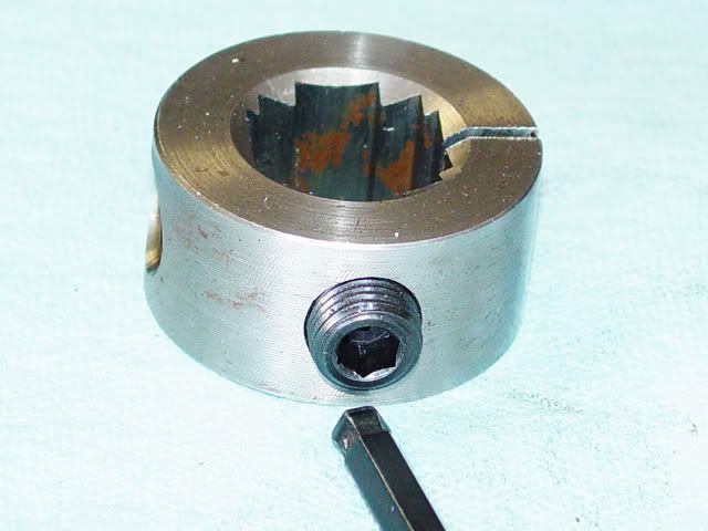
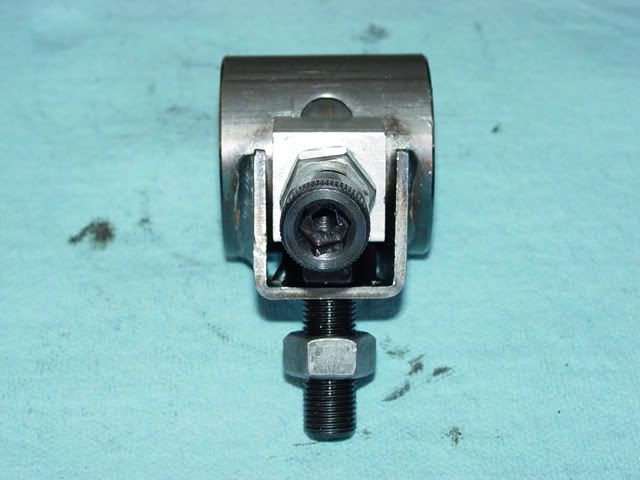
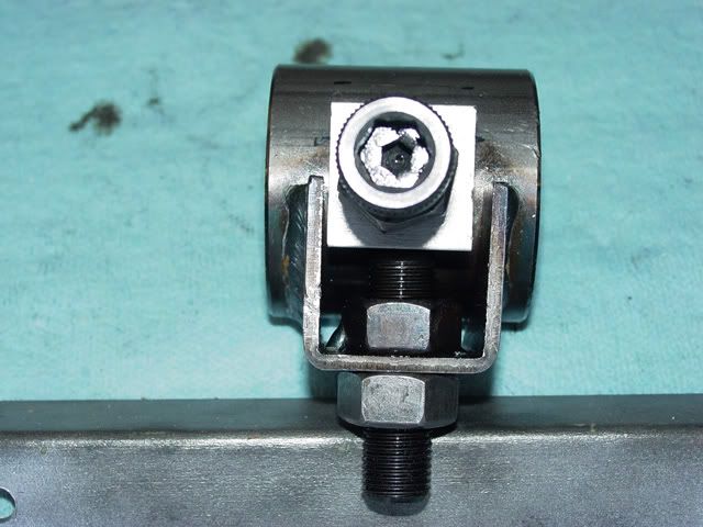
In this picture you can see both holes. Inside of the U-shaped part of the housing there is a slot and in this slot the open hole of the center section should be seen. When reinstalling the parts, the adjuster block is placed over the hole with the pointed set screw w/nut is slid down the hole in the adjuster block and the adjuster screw is threaded into the center section (it is called the disc on the Bugpack instructions and the Sway-a-way calls it the adjuster.. I think). The Sway-A-Way does not seem to have the short plug so other than not using the wrong threaded hole in the center section, it probably may be eliminated; I left mine in place but before I go too far with the welding I will slide the spring pack into the adjuster to see if it causes a problem.
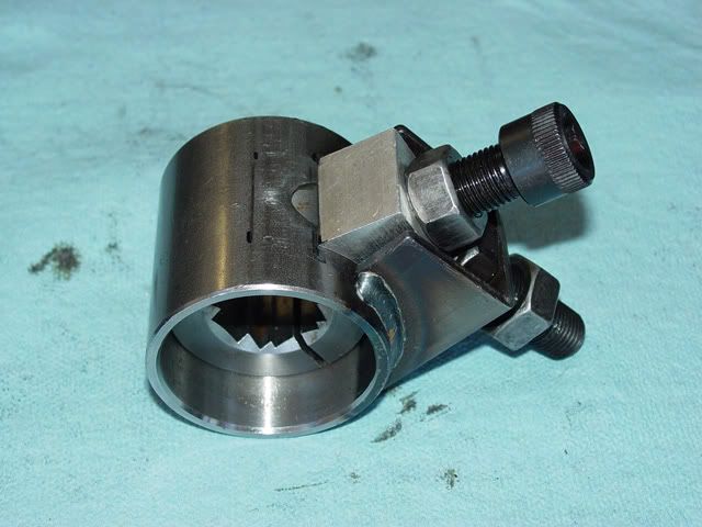
When reassembled, the gap in the center section should be sitting like this if you are going to do a King and Link beam.
This is the setting for a ball-joint beam.
Now comes the fun part: setting the adjuster itself before installing it in the beam.
In this shot you see part of the slot in the housing that allows a certain amount of movement of the block, hence the spring pack. First, let me say that the second line I was so worried about that I laid in on the last post, while its dimensions are important they are not fanatically important (see, after having done it once then the instructions are clearer now… isn’t that the way it usually is? I think that is why they say it should be done by an expert [an expert is someone who was a “pert” or “spert”, I am not sure of the name so I have given both, but has gone through therapy and is not one anymore]) as there is some finagling with the settings you can do. First of all, the second line is to be the centerline of the adjusting bolt and no, it is not easy to mark the line where you want it on the housing; it is not that critical.
You can set the adjuster to allow you to lift up the front of the car only or drop the front end of the car only or to do both; I have chosen to do both. In this picture, the adjuster is set to allow the car to be lowered (or vice-versa). At the full down setting I made two little tick marks at the front of the adjusting block on the housing.
In this shot, I adjusted the block fully in the other direction and again, made two marks.
To be able to raise and lower I moved the adjusting block halfway between them and locked the block down so it wouldn’t move using the set-screw and its locking nut.
This shows it with the other lock in place.
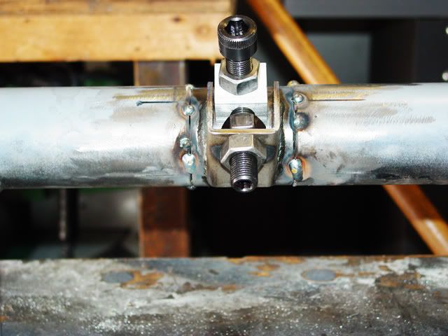
Then, believe it or not, I tacked the adjuster in place using more than enough tacks to keep thing solid when moving the beam around.
Edit: I did not mention that the adjusters are tacked in place only for right now as the torsion springs must be installed to check for alignment and proper location of the locking dimples for the trailing arms. I also failed to note that the locking screw that goes though the adjuster block and into the center section to lock the spring stack in place should only be into the center section far enough to hold the center section in place but not far enough to stop the spring stack from passing though.
If you don’t get the locking screw in deep enough to hold the center section in place you could push it out of the adjuster housing and then you are in deep doo-doo and will have to cut the whole thing apart (as far as I know which seems to me to be correct).
When sliding the spring stack though the center section you have to keep the leading ends of the splines together somehow. Methods I have heard used are both good and bad but you can’t very well tie or tape the leading end of the stack together as the fit is too tight through the center section. Super gluing the ends of the splines together, for a very short distance, sounds OK as long as that part of the stack is very clean so it will hold. Running a tack weld is probably not a good idea because of the heat but I have heard of it being done… I don’t recommend it.
Once everything is checked out then you should be able to finish weld the adjuster in place. If you leave the spring stack in place then remember not to get too much heat into the tube/adjuster block to ruin the individual splines.
Now on to the lower beam and it should be done unless someone has any other bright ideas.
Lee
This might receive some editing as I expect some comments. Thanks for reading this; I do expect to post pictures of the finished product.


