Page 3 of 5
Bosch alternator
Posted: Thu Apr 19, 2007 2:13 pm
by shopteacher
MNAirHead wrote:I'm going to split your question.. someone else will want to know.. which exact altenator are you using?
from the alternator label
BOSCH
New Alternator
AL 82N
804 867
thoughts on the inline resistor on the coil?
Posted: Sat Apr 28, 2007 7:13 am
by david58
Posted: Mon Jun 11, 2007 4:43 am
by MNAirHead
Posted: Fri Jun 22, 2007 7:54 am
by shopteacher
MNAirHead wrote: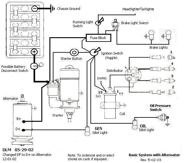
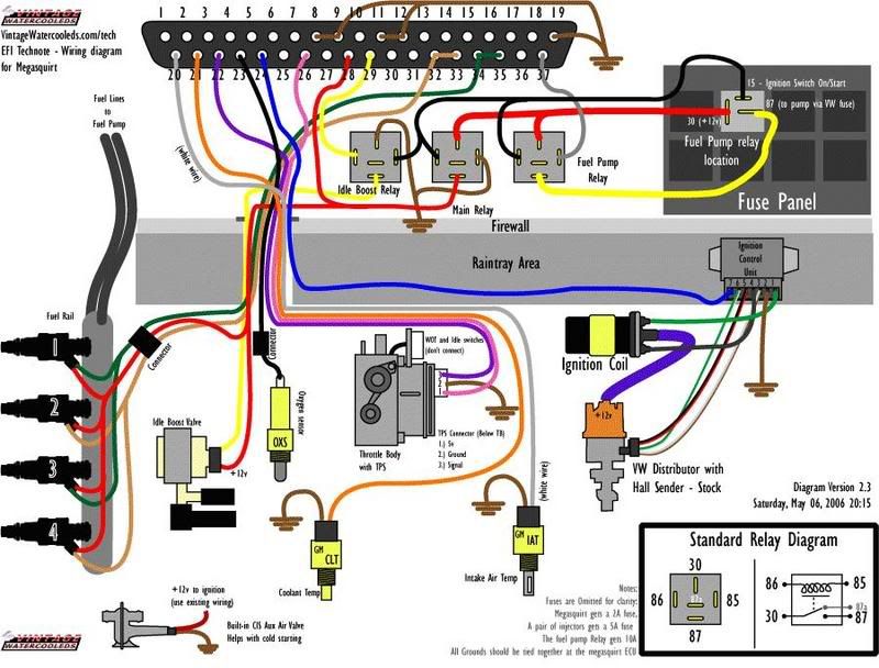
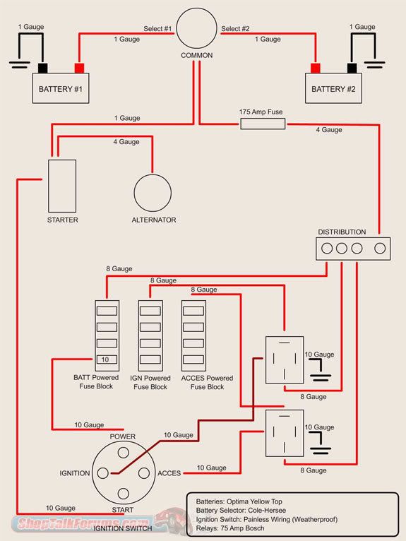
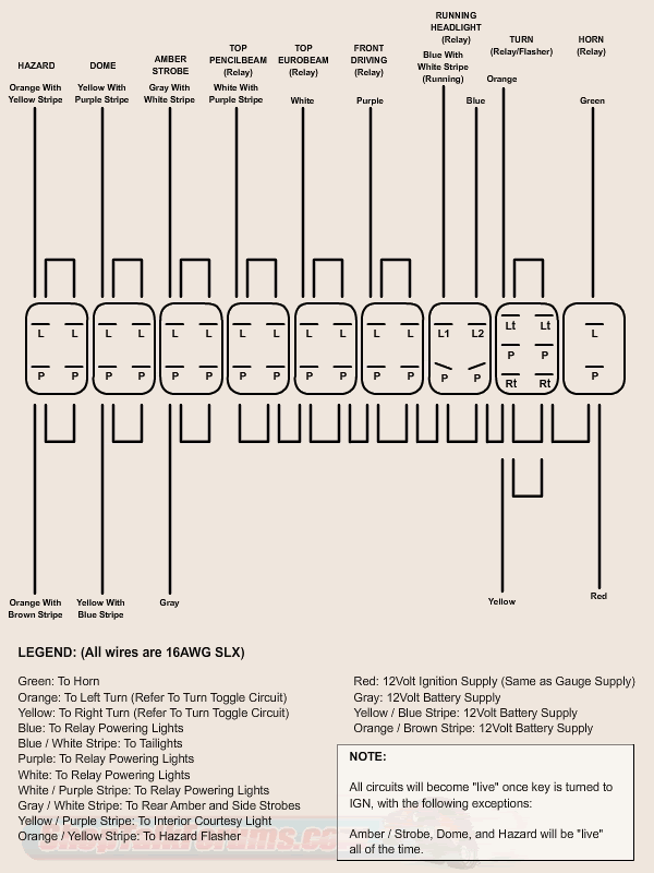
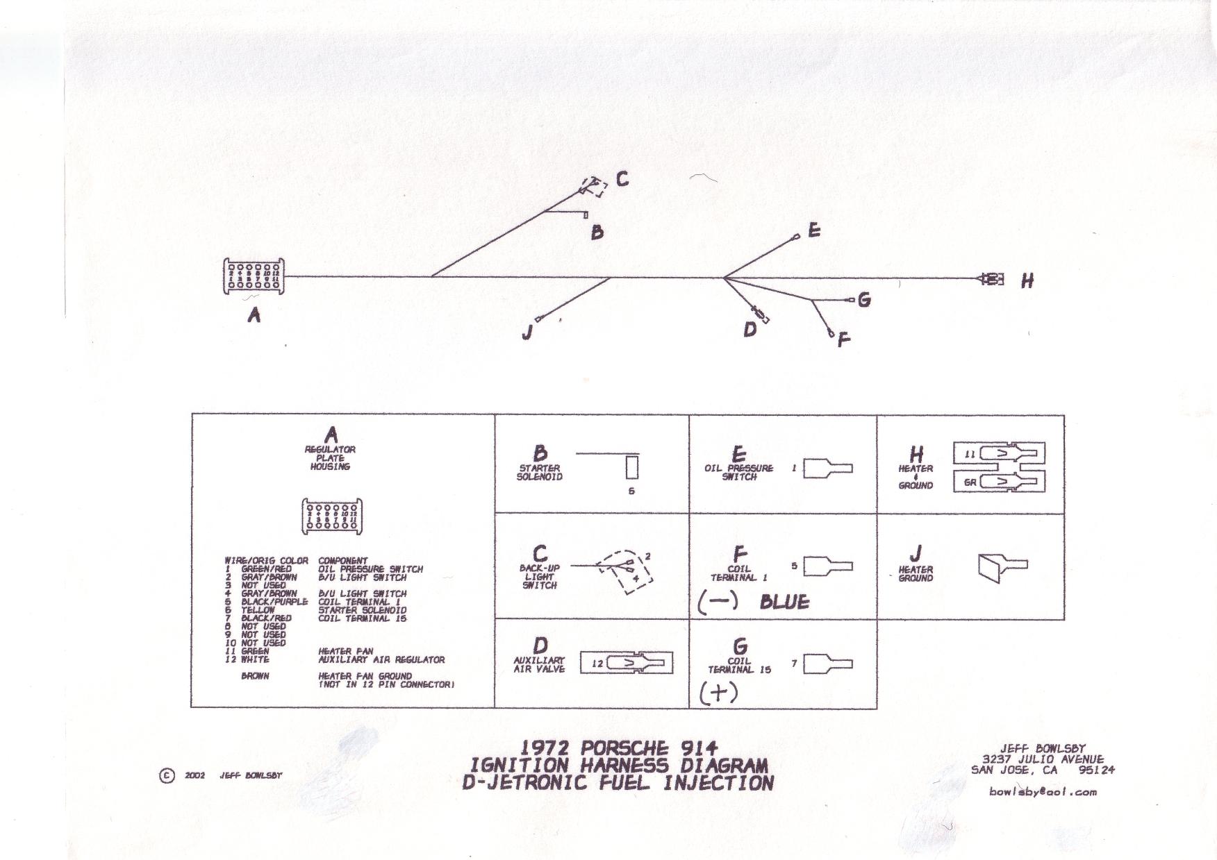
Stephanie aka "NYRO"(16) used this diagram to wire our 1835 into our 4 seater project


it worked the first time... AND the second time
Great Job Nyro!
Posted: Sun Jun 24, 2007 9:57 am
by MNAirHead
Posted: Sun Jun 24, 2007 9:58 am
by MNAirHead
Posted: Sun Jun 24, 2007 10:01 am
by MNAirHead
Posted: Sun Jun 24, 2007 10:08 am
by shopteacher
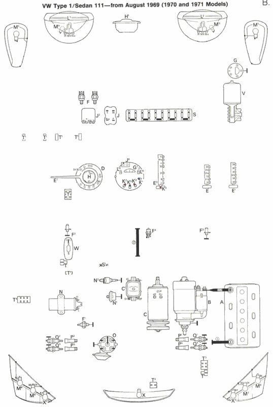
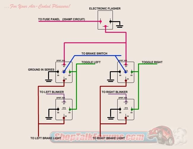
why was the brake light circuit highlighted?
Posted: Sun Jun 24, 2007 10:48 am
by MNAirHead
reply to a post
Posted: Sat Jul 28, 2007 6:22 am
by david58
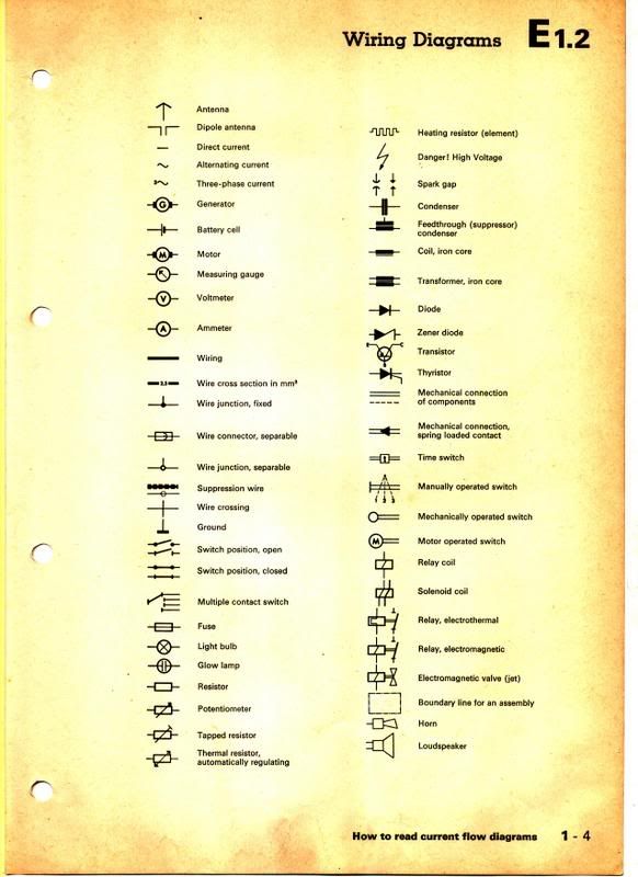
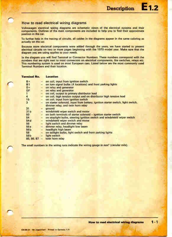
This is a PDF file worth saving it explains how to read a diagram. It is only 7 pages long.
http://www.bentleypublishers.com/images ... iagram.pdf
Posted: Fri Nov 23, 2007 9:26 am
by MNAirHead
Leatherneck wrote:
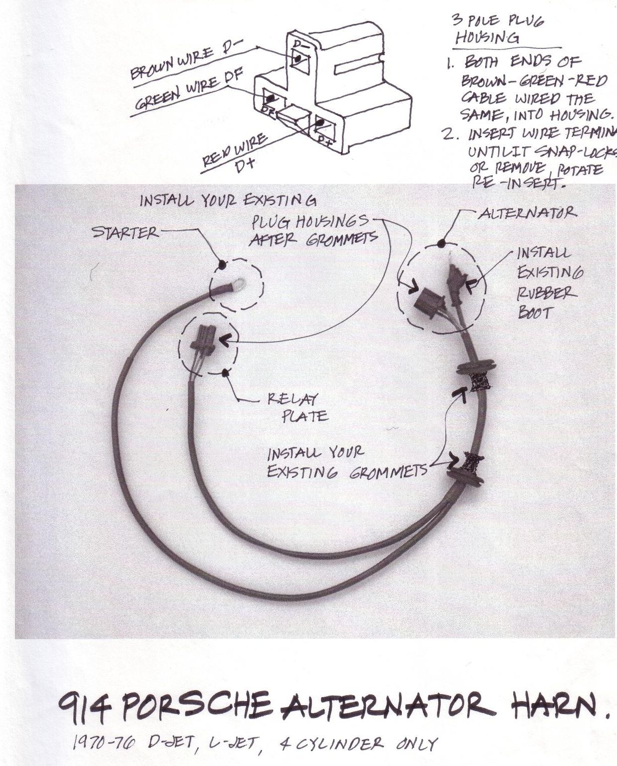
Insure wiring is routed as above.
First, take the generator belt off so generator rotates freely then Be sure a good ground is made between the regulator base and the mount. Scrape the mounting area before installing. On most applications there is a ground wire from the Generator to a positive ground.
A ground wire can be connected from Generator to the Regulator base with a sheet metal screw in the hole provided in Regulator base.
After Installing Generator or Regulator
#1 Reconnect the ground strap to the battery.
#2 Before starting the motor you should Polarize the generator as follows.
Momentary touch a jumper wire from D+ terminal to the B+ terminal.
Do not touch the DF terminal as the Regulator will be damaged. The generator will start to spin, disconnect wire and you should be good to go.
Posted: Fri Nov 23, 2007 9:43 am
by MNAirHead
Badbugtwo wrote:Here is a pic of how they are put together...

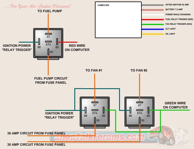
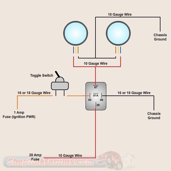
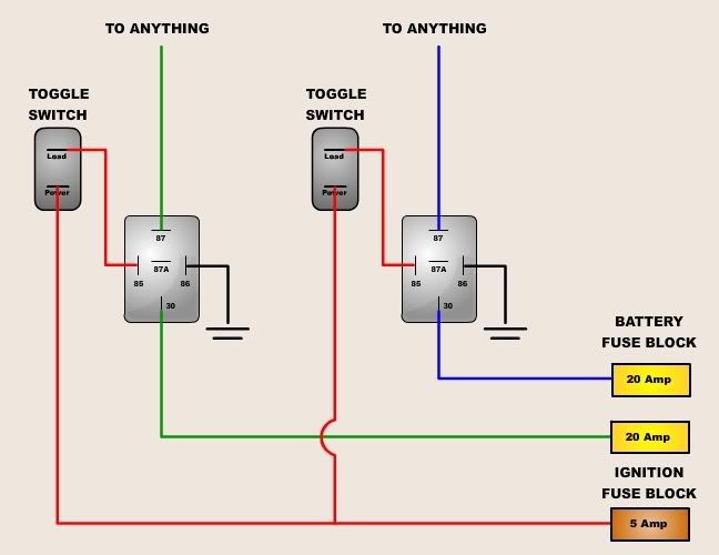
To further elaborate, the 86 terminal is the positive side of the electromagnetic coil and 85 the ground side. This coil is what controls the switching action and takes less than 0.2 amps to activate. It can be controlled by either a power side or ground side switch or in some rare cases both.
The 30 terminal is a common with the 87a being connected to it when de-energized and then the 87 when powered up. You can activate a circuit either on the power or ground side. Usually they are rated for 20 or 30 amps.
Hope this helps!

Posted: Sat Dec 29, 2007 11:32 pm
by david58