One at a time unless you want to put it together then take it apart to shim the off set.Ol'fogasaurus wrote: Do you put the arms in the beam as an assembly or one at a time then put the spindle in last? I was planning on installing them one at a time.
Basic Off-road Ball-Joint Beam rebuild PT 2 starts on p. 13
-
david58

- Moderator
- Posts: 14101
- Joined: Sun Oct 23, 2005 6:14 pm
Re: Very Basic Off-road Ball-Joint Beam rebuild
Hot, humid air is less dense than cooler, drier air. This can allow a golf ball to fly through the air with greater ease, as there won't be as much resistance on the ball.
-
BAJA-IT
- Posts: 2046
- Joined: Tue Oct 07, 2008 5:02 pm
Re: Very Basic Off-road Ball-Joint Beam rebuild
I put the arms on one at a time, then put the spindle on. I don't think you could put the arms in if they were bolted to the spindles. Sense I have adjusters on the beam, I turn them out to take the tension off the arms, this makes it easier to lift the upper arm to get it in the spindle, then I readjust the adjusters once the ball joints are tightened up.
BRAT Motorsports #936
Bolt Center: Salt Lake City, Ut
ACE: Air Cooled Engineering, now Black Line Racing
Bolt Center: Salt Lake City, Ut
ACE: Air Cooled Engineering, now Black Line Racing
-
Ol'fogasaurus
- Posts: 17881
- Joined: Mon Nov 13, 2006 10:17 pm
Re: Very Basic Off-road Ball-Joint Beam rebuild
That is good to know as it was my plan too.
Lee
Lee
-
Ol'fogasaurus
- Posts: 17881
- Joined: Mon Nov 13, 2006 10:17 pm
Re: Very Basic Off-road Ball-Joint Beam rebuild
I haven't forgotten about this build, I just have had other things going on that took me away from it. I now have the doubler on the inside of the shock mount pretty much welded in place and this morning I finished welding in the in side part and the outside of the stop. I am waiting for the area to cool before starting on locating, shaping and fitting the bracing of the stop.
I am finding that I weld better sitting down and weld in short stints so I don't start pushing things to get done and make things worse.
I am seriously considering taking classes on TIG welding but I missed this quarter so that will start when they start over. I have to go up and find out just what is going on as it they are taught at the college iabout 20 miles away. I'm not sure if I can get in as a hobbyist learner and not looking to make a living at it. Cost of the class too is important as i am not spending $2K+ to learn TIG.
Lee
-
Steve Arndt
- Posts: 7420
- Joined: Sat Mar 10, 2001 12:01 am
-
Ol'fogasaurus
- Posts: 17881
- Joined: Mon Nov 13, 2006 10:17 pm
Re: Very Basic Off-road Ball-Joint Beam rebuild
Thanks Steve, the tease looked good but he is asking for info I don't want to give right now (email address). I'm in the process for having to have both my computers gone though right now and I don't want to take the chance of getting them crapped up right-a-way.
Lee
Lee
-
Steve Arndt
- Posts: 7420
- Joined: Sat Mar 10, 2001 12:01 am
Re: Very Basic Off-road Ball-Joint Beam rebuild
all his how to videos are hosted on you tube for free.
http://www.youtube.com/user/weldingtipsandtricks
http://www.youtube.com/user/weldingtipsandtricks
-
Ol'fogasaurus
- Posts: 17881
- Joined: Mon Nov 13, 2006 10:17 pm
Re: Very Basic Off-road Ball-Joint Beam rebuild
Thanks Steve, very interesting and informative. Gotta do it for sure!
Lee
Lee
-
Ol'fogasaurus
- Posts: 17881
- Joined: Mon Nov 13, 2006 10:17 pm
Re: Very Basic Off-road Ball-Joint Beam rebuild
I finally got some uninterrupted time in the garage today (my step-daughter is in the hospital with an unknown something) so no redirection of my lack of initiative and horizontal decision making.
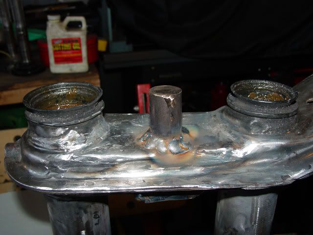
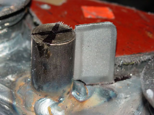
On my last post I said I have the stud welded in place, not the best looking job but it should hold the light tippy-taps that could happen as I cautiously drive on the dunes.
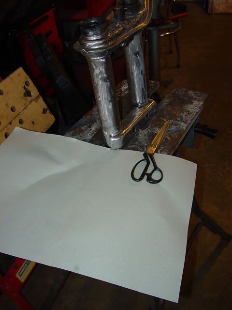
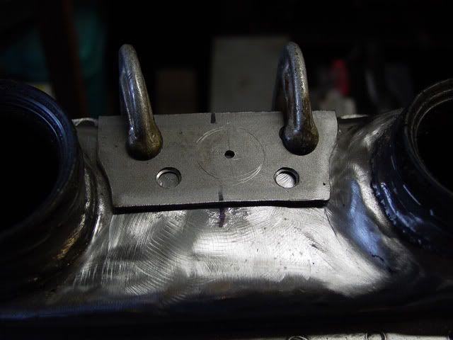
Just-in-case, I decided to add some gussets behind the stop where loads could be applied. I started out by finding some thick paper to make a template out of. I was looking more for card stock but ended up with some construction paper.
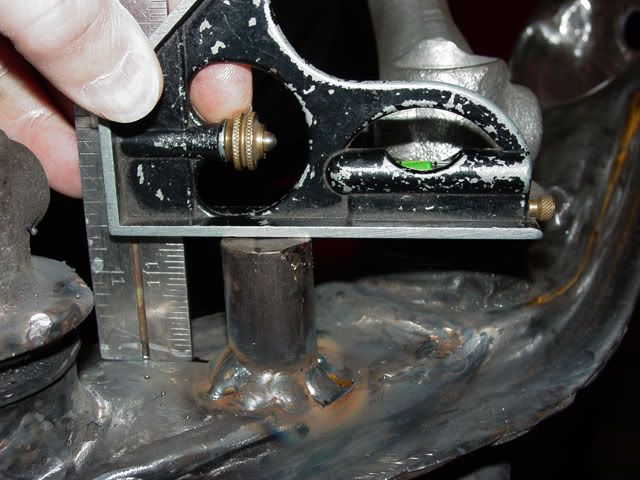
To find the height I took my tri-square and set it on top of the stop and away from the welding and the doubler I had added and come up with a measurement of about 1 ½ inches. I then got a measurement of how far to the rear it should go and about an inch should be OK. There is going to be a taper to the lower leg here so I allowed for that in both measurements.
I then put the trailing arms back in and tried to get a contact spot and angle of contact. This is the lower arm and as you can see it is a bit long and the hook doesn’t match up well; I broke it loose and held it in place (the location is not yet critical so almost anywhere along the skirt of the trailing arm will do.
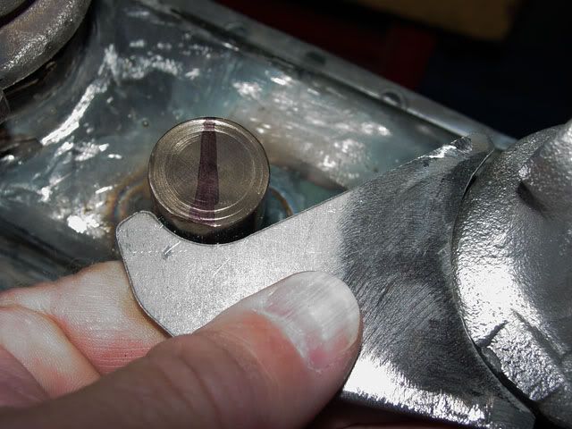
As you can see, the upper trailing arm fits a little better and with some minor fitting matches the skirt of the trailing arm quite well.
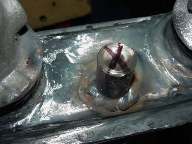
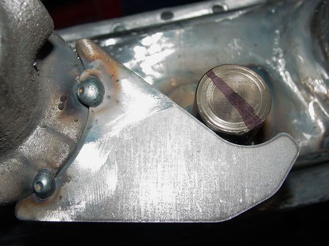
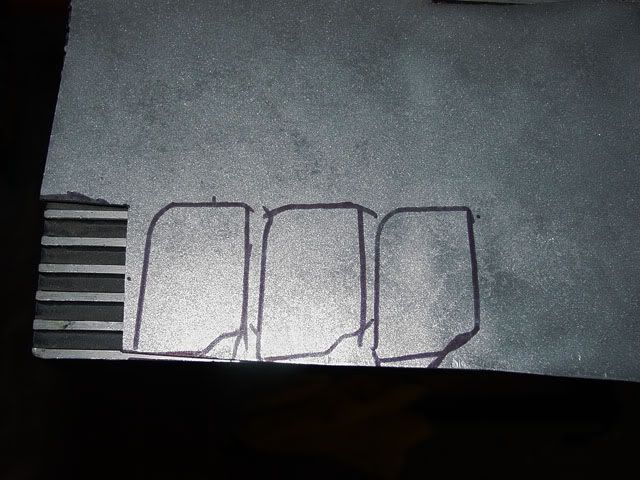
This is the stop with the contact places marked and perpendicular lines were drawn across the stop. Those lines were continued in the shock mount itself and are going to be the locations of the gussets.
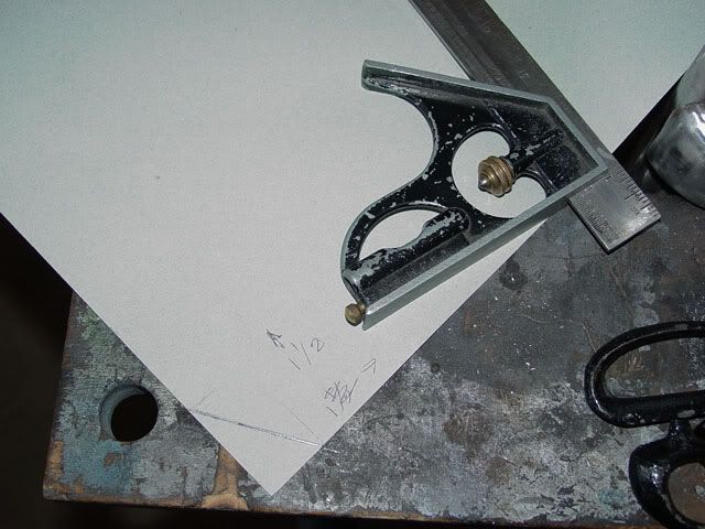
You can’t see it real well, but this is the template for cutting the gusset. I suspect that the other side will be able to use the same gusset. Got to go find some steel, of the proper thickness, for the gussets before I go any farther.
Lee
On my last post I said I have the stud welded in place, not the best looking job but it should hold the light tippy-taps that could happen as I cautiously drive on the dunes.
Just-in-case, I decided to add some gussets behind the stop where loads could be applied. I started out by finding some thick paper to make a template out of. I was looking more for card stock but ended up with some construction paper.
To find the height I took my tri-square and set it on top of the stop and away from the welding and the doubler I had added and come up with a measurement of about 1 ½ inches. I then got a measurement of how far to the rear it should go and about an inch should be OK. There is going to be a taper to the lower leg here so I allowed for that in both measurements.
I then put the trailing arms back in and tried to get a contact spot and angle of contact. This is the lower arm and as you can see it is a bit long and the hook doesn’t match up well; I broke it loose and held it in place (the location is not yet critical so almost anywhere along the skirt of the trailing arm will do.
As you can see, the upper trailing arm fits a little better and with some minor fitting matches the skirt of the trailing arm quite well.
This is the stop with the contact places marked and perpendicular lines were drawn across the stop. Those lines were continued in the shock mount itself and are going to be the locations of the gussets.
You can’t see it real well, but this is the template for cutting the gusset. I suspect that the other side will be able to use the same gusset. Got to go find some steel, of the proper thickness, for the gussets before I go any farther.
Lee
-
BAJA-IT
- Posts: 2046
- Joined: Tue Oct 07, 2008 5:02 pm
Re: Very Basic Off-road Ball-Joint Beam rebuild
Don't forget that when you set the stops on the arms you need to have the spindles bolted to the arms so you know where on the arm the stops need to be. Also you need to turn the spindle as though you were turning the wheels lock to lock, as this changes where the ball joint bottoms or tops out at.
Looks like I will be doing this for the race car shortly. I know the beam is bent, but I think it's bent more now after the tree incident at the last race.
Looks like I will be doing this for the race car shortly. I know the beam is bent, but I think it's bent more now after the tree incident at the last race.
BRAT Motorsports #936
Bolt Center: Salt Lake City, Ut
ACE: Air Cooled Engineering, now Black Line Racing
Bolt Center: Salt Lake City, Ut
ACE: Air Cooled Engineering, now Black Line Racing
-
Ol'fogasaurus
- Posts: 17881
- Joined: Mon Nov 13, 2006 10:17 pm
Re: Very Basic Off-road Ball-Joint Beam rebuild
In the last post I showed a pattern I had developed but it was incomplete which I didn’t but should have mentioned. I had a few minutes out in the shop so I found some 14 ga flat stock and put it in the bead blaster to clean in up and it was ready to whack up for a gusset.
I cut the pattern out of the construction pattern using the top and base for a guide, not the diagonal. The top of the triangle would have been too thin to weld up to the 7/8 round stock with all the head that would be used.
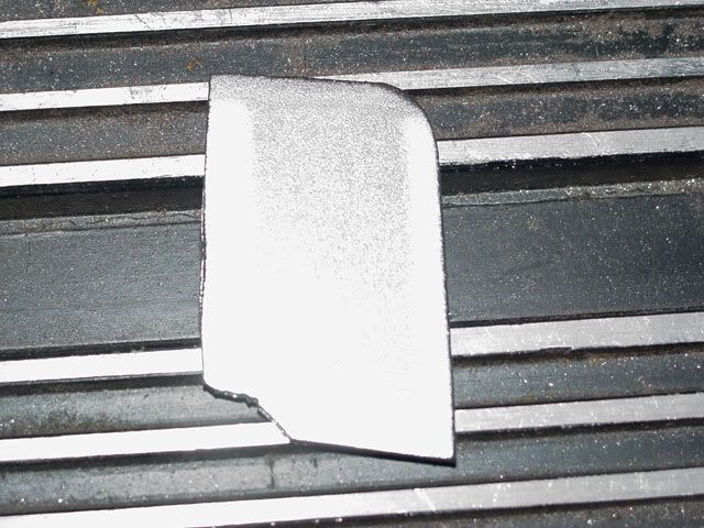
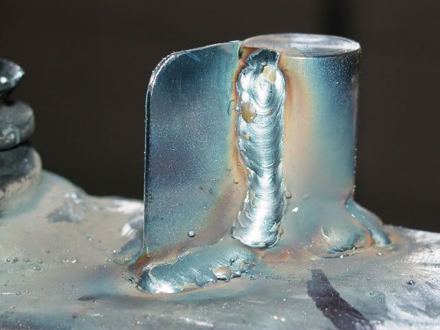
This is the shape I came up with; long enough and deep enough to be a gusset and some extra for trimming and fitting. I have one of those inexpensive horizontal/vertical band saws so I used it for the rough in work. I also have a Delta fairly light weight 4 X 36 belt sanders mounted on a table to do some minor work and also used my grinding wheel for the heavier work. It took about 10 minutes between t he belt sander and the grinding wheel to get the fit close enough to weld.
This is the gusset in place. I might make three others off this pattern as it is general enough to use… I think. I plan on using a heat sink behind the gusset to keep it from melting while I weld it in place and I will weld from both sides just in case.
BAJA-IT, Thanks for the reminder. I haven't pressed the ball-joints in yet but that is a to-do after I get the posts mounted and braced on both sides. I forget right now who came up with the idea of using all-thread to replicate the shocks but using bolts on both sides. I will go to full travel of the ball-joint then back off some before I mount the stops. This will be done for both compression and extension.
I hope than trees do not continue to jump out at you in the future. It is funny how agile and quick moving they can be at times.

Lee
I cut the pattern out of the construction pattern using the top and base for a guide, not the diagonal. The top of the triangle would have been too thin to weld up to the 7/8 round stock with all the head that would be used.
This is the shape I came up with; long enough and deep enough to be a gusset and some extra for trimming and fitting. I have one of those inexpensive horizontal/vertical band saws so I used it for the rough in work. I also have a Delta fairly light weight 4 X 36 belt sanders mounted on a table to do some minor work and also used my grinding wheel for the heavier work. It took about 10 minutes between t he belt sander and the grinding wheel to get the fit close enough to weld.
This is the gusset in place. I might make three others off this pattern as it is general enough to use… I think. I plan on using a heat sink behind the gusset to keep it from melting while I weld it in place and I will weld from both sides just in case.
BAJA-IT, Thanks for the reminder. I haven't pressed the ball-joints in yet but that is a to-do after I get the posts mounted and braced on both sides. I forget right now who came up with the idea of using all-thread to replicate the shocks but using bolts on both sides. I will go to full travel of the ball-joint then back off some before I mount the stops. This will be done for both compression and extension.
I hope than trees do not continue to jump out at you in the future. It is funny how agile and quick moving they can be at times.
Lee
-
Ol'fogasaurus
- Posts: 17881
- Joined: Mon Nov 13, 2006 10:17 pm
Re: Very Basic Off-road Ball-Joint Beam rebuild
I got some more shop time today so I decided to cut the other gussets.
Using the one gusset I cut and fit, I traced the shape on to the same sheet of metal and cut them out, cleaned them up and put two away for the other side of the beam. I then fit the remaining gusset to the beam on the marks I had made before.
This shows the first gusset welded in place, on both side, although you can’t see it, it is welded up too.
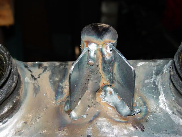
After some additional fitting to the last bracket, it did help some to cut all of them at the same time but the relief for the weld is different at each position so that has to be accommodated, I welded it in place; again, welding it on both sides. The shape is not the final shape as I am going to trim the upper part of the gusset back some, more of a triangle like shape with a radius for some additional support and to eliminate any possibility of flexing of the gusset.
Lee
Using the one gusset I cut and fit, I traced the shape on to the same sheet of metal and cut them out, cleaned them up and put two away for the other side of the beam. I then fit the remaining gusset to the beam on the marks I had made before.
This shows the first gusset welded in place, on both side, although you can’t see it, it is welded up too.
After some additional fitting to the last bracket, it did help some to cut all of them at the same time but the relief for the weld is different at each position so that has to be accommodated, I welded it in place; again, welding it on both sides. The shape is not the final shape as I am going to trim the upper part of the gusset back some, more of a triangle like shape with a radius for some additional support and to eliminate any possibility of flexing of the gusset.
Lee
-
Ol'fogasaurus
- Posts: 17881
- Joined: Mon Nov 13, 2006 10:17 pm
-
Ol'fogasaurus
- Posts: 17881
- Joined: Mon Nov 13, 2006 10:17 pm
Re: Very Basic Off-road Ball-Joint Beam rebuild
I got some time in the garage today so I did some work on the beam rebuild. The one side is pretty much done so it is off to put the post in the other side. I had cut the shape for the second side when I did the first side so it was just a matter of relieving the two ends to fit in. I also had to take a bulge/bend out of the doubler with took a couple small whacks with a small ball peen hammer. I also had a bulge in the shock tower which I also massaged.
Like the other side I clamped the doubler in place and located the post using both the measuring method and installing the trailing arms and using the hooks on them to locate the post, then scribed it, found the center of the hole marked it and drilled a 1/8 inch pilot hole.
When I drilled the pilot hole I also drilled four holes for plug welds to add to the rigidity of the doubler. I drilled though which gave me some crap on the bottom so I turned the place over and drilled back though with a larger drill. I then back cut the pilot hole for the post, turned the doubler back over and countersunk the 4 holes for the plug weld.
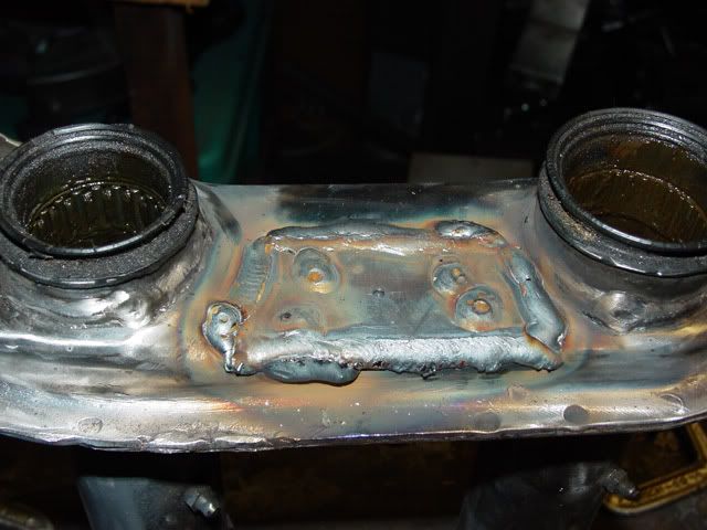
I then welded things up. Not the best looking as I got wavy at the end and had to do a fill so that there would not be any places for salt water to side. If I get some time in the garage the other doubler should get added, the welds dressed where it is important and maybe even the post welded in. Wifee-poo always has a project or two she wants done just in case I need some rest from the other projects she has.
And no, I haven’t forgotten to do the seams. I may or may not have a trick on that but I have to try it out first.
The new battery less auto-darkening welding helmet has sure helped as well as some oversized readers to see what I am doing.
Lee
Like the other side I clamped the doubler in place and located the post using both the measuring method and installing the trailing arms and using the hooks on them to locate the post, then scribed it, found the center of the hole marked it and drilled a 1/8 inch pilot hole.
When I drilled the pilot hole I also drilled four holes for plug welds to add to the rigidity of the doubler. I drilled though which gave me some crap on the bottom so I turned the place over and drilled back though with a larger drill. I then back cut the pilot hole for the post, turned the doubler back over and countersunk the 4 holes for the plug weld.
I then welded things up. Not the best looking as I got wavy at the end and had to do a fill so that there would not be any places for salt water to side. If I get some time in the garage the other doubler should get added, the welds dressed where it is important and maybe even the post welded in. Wifee-poo always has a project or two she wants done just in case I need some rest from the other projects she has.
And no, I haven’t forgotten to do the seams. I may or may not have a trick on that but I have to try it out first.
The new battery less auto-darkening welding helmet has sure helped as well as some oversized readers to see what I am doing.
Lee
-
Ol'fogasaurus
- Posts: 17881
- Joined: Mon Nov 13, 2006 10:17 pm
Re: Very Basic Off-road Ball-Joint Beam rebuild
(no pictures) I got some time the other day to do some work on the beam. I started drill the hold for the post to put the opposite side support in for the post. Like the other side, I started to enlarge the pilot hole for the post and finally got it to the required 7/8" diameter hole. I then put the tool in that I built and drilled the hole for the opposite side of the shock mount to fit on. With two sprained wrists I finally got the hole drilled and the post to fit through and be perpendicular. I then put the inside doubler on the post and clamped it down and measured the height of it sticking out on the other side; I put the trailing arms in and using the hooks against the flanges of the trailing arms checked for good contact. The contact of either of the hooks was minimal with no post material sticking out over the hooks; in-other-words, no room for error.
I had noticed before that the inside of the shock mount was not flat but slightly bowed, kind of like there was an explosion inside but didn't think much of it. Once the inside doubler and post were clamped in place I got looking at the inside of the shock mount and the end of the doubler was lifted to the point that I could see some where between 1/8 and 1/4 inch of the post as it went into the hole. I laid the beam out flat and carefully tapped the bulged area until it was flat. When I tried the post in place again, the inside hole was now too tight so a quick pass with the 7/8” drill bit and the post slid in very nicely; rechecking things out everything is now sitting pretty much correctly.
I was curious as to why this area of the beam was bulged, and why the bulge was on a slight diagonal until I remembered that this is the beam that was on my buggy when I hit a no-see-um and collapsed the front suspension so far. This same side (driver’s side) where the shock jammed itself into its dust shield and locked the suspension down tight and it tool a long crow bar to break things apart. The hit must have pushed the lower tube up some, enough to cause the area of the shock tower between the upper and lower beams to bend and deform the formed stock shock tower in this area.
Another good reason to put the stops in
Lee