My name is Doug...and yes, I have a bug.
Actually I have been working on a complete body off restoration of a 1960 sedan for my wife for the last three and a half years. I have been lurking around thesamba.com for some time and recently posted this "how-to" thread regarding the "interestingly engineered" horn system that plagues the 60-61 beetle.
Yesterday, samba member RSA204 asked if I could post it here in the electrical forum and I said I'd be happy to, so here it is. I hope somebody finds it useful.
--------------------------------------------------------------------------------------------------------------------------------------------------------------------------
So…you removed your steering wheel and took it apart for whatever reason, and now you find yourself looking at this and scratching your head…

Well, I did the same thing, and I could not find ALL the information I needed by searching the forums. What i did find, however,
was that several others, at one time or another, had the same questions I did, but were not finding the help they needed,
so I thought I'd try to shed some light on the subject of the 60-61 horn issue.
First off, let me say that this is NOT a difficult system. A tad bit over engineered...yes. But by no means is it rocket science.
This is what I did, and my horn works perfectly. I hope that the following step-by-step series of photos will be helpful to someone.


:IMPORTANT: When installing the steering wheel, slide it onto the shaft until the splines engage, then, BEFORE pushing it all the way down, rotate the wheel 90 degrees either way, then push it on all the way. If you don't do this you could bend the tab on the canceling mechanism. How do I know this you ask? Well...some things in life we have to learn the hard way.


Make sure the brown wire that attaches to the end of the steering column tube, under the fuel tank, has a good, clean connection.

Here's a very basic explanation of how it all works, but first, please understand I'm not an electrician, and I couldn't tell you the difference between wattage, voltage, current and all that stuff, and I'm quite sure there's a better way to explain this so please bear with me and my simplicity.
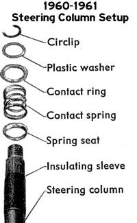
The brass contact ring with the partial cutout sits on top of the contact spring, which sits in a collar (spring seat), which sits in the bearing that is pressed into the end of the steering column tube. This whole assembly is actually part of the electrical circuit and is isolated from the steering column by a black plastic sleeve. If this sleeve has a spot worn through to the metal, which they often do, your horn will beep intermittently as the steering wheel is turned. "ANNOYING"
Current flows through the steering column tube, the bearing, the spring seat, the contact spring, the contact ring and finally to the metal plate on the back of the steering wheel that has the three contact points...and that is where the circuit is broken...until you push your horn ring.
When you do, one of the three brass pins (depending which side of the ring you push) is pushed down, making contact with the corresponding contact point, thus completing the circuit through the steering wheel, down the steering column and across the jumper on the steering box which is grounded to the chassis.
Now, because the horn is grounded to the chassis as well, and it has a hot wire attached to it.......................BEEP!
As you can see, in order for the electrical circuit for the horn to be completed, the current flow really has to run the gauntlet, and all it takes is one little something that's boogered up to make the system fail.
What's most important is all the little things intended to insulate "this from that" and the other thing.
ALL the plastic washers, the white plastic piece under the metal plate on the back of the wheel, the black insulating sleeve on the column etc, etc.
Pretty much everything in this setup is specific to 60-61 accept maybe the horn its self, however, for other years the principle is the same, just configured a little differently.
It all may seem a bit daunting if your unfamiliar with how it all works, but rest assured, it's not that bad.
Good luck.




 It is also in the sticky in the newbie forum.
