Link Pin Shim Chart
-
david58

- Moderator
- Posts: 14101
- Joined: Sun Oct 23, 2005 6:14 pm
Link Pin Shim Chart
Anyone know where it is?
Hot, humid air is less dense than cooler, drier air. This can allow a golf ball to fly through the air with greater ease, as there won't be as much resistance on the ball.
-
Leatherneck

- Moderator
- Posts: 17104
- Joined: Sat Jul 01, 2006 6:47 pm
-
david58
- Moderator
- Posts: 14101
- Joined: Sun Oct 23, 2005 6:14 pm
Re: Link Pin Shim Chart
KTPhil wrote:
Anyone got the shim table handy?

Michael Fischer wrote:

djkeev wrote:Here is some info that should help you get started.
Remember that the Ghia is a Type I VW
I've gone though some posts that I've seen in the past and either linked or cut and pasted into here. Sorry about the length but it can be easier to read in one place. I've given credit where I can for the original sources of info where I know it, none of this is my info. Do a search here on Samba, you'll find dozens of posts on this topic but this information seems to be the most informative.
If anyone can add to this, please do, this isn't at all inclusive. While the question was for a ball joint car, one of the descriptions is for link pin. I added a 2nd post with ball joint instructions from the Bentley.
From glutamoto...
also look here....
http://www.thesamba.com/vw/forum/viewto ... =alignment
------------------------------------------------
drscopes instructions on setting toe
"Doing the strings helps if you have 4 jack stands.
With the car parked on a fairly level surface...
Place a jack stand at each corner of the car. Then move those stands out front and out back about 10 feet if you have the room.
Now tie a string from the stand at the right front to the stand at the right rear.
Then tie another string from the stand at the left front to the one at the left rear.
The strings are going to be about 12 inches off the ground. Then measure over from the string to the side wall of the tire. You want that distance to be the same for the front side of the tire and the rear side of the tire.
When the distance is the same, the string is now parrallel to the tire and is pointing in the same direction that the tire is steering in.
_________________
Pull the stands so the strings are tight and adjust the height so it is as close to the center of the wheel as you can get it.
Now, move the rear stand so you can measure from the string to the tire on the rear side of the tire. Then move the front stand so you get the same measurement from the string to the front side of the tire.
Now the string is parrallel to the tire. Do the same on both sides.
Now you can sight down the strings to see which way the tire is pointing in relation to toe. Or, you can measure from one string to the other in front and in back of the car.
The longer the strings, the easier it will be to see where they are pointing.
Understand?
Now you can move your axle in the spring plate and restring it to see where it is.
On a swing axle, it helps if the axles are level with the ground. Toe will change as the suspension moves up & down. So make sure you have the car close to the ride height you will be running when you string it.
If you can't get the toe settings you want, you may need to slot the holes in the spring plates.
And yes, forget about finding a shop that can understand how a swing axle works and align it properly!"
_________________
Added to this was....
"To make sure that the strings are parallel to the centreline of the car, check that:
1. The distance between the strings is the same at the front as at the rear of the car.
2. The distance between the string and the centre of the driver's side front wheel is the same as between the other string and the centre of the passenger's side front wheel.
3. The distance between the string and the centre of the driver's side rear wheel is the same as between the other string and the centre of the passenger's side rear wheel."
_____________________________________
Yet another drscope quote...(he knows his stuff)
"Got tools and a brain cell? If so, you can do this your self and save a lot of cash. The only thing you may have to send out is having the new ball joints pressed into the trailing arms.
Here is info I have passed along mostly for the king & link pin guys, but this will also apply to alignment of the ball joint cars once the beam is assembled and installed. The only difference is you need to also set your camber with the eccentric in place of the shims.
--------
First you need to understand the 3 parameters of a front end alignment so you can understand what you need to do.
Let's start with camber. Camber is the angle in which the wheels stand. Straight up is zero camber. If the wheels lean in at the top like this / \ this is called NEGATIVE CAMBER. If the wheels lean out at the top like this \ / this is called POSITIVE CAMBER.
Camber has a direct effect on how well the car turns in. Too much positive and the car tends to push or slide and not turn when you turn the steering wheel. Too much negative and it turns in too quick which may cause the rear of the car to break away. It also eats up your tires.
On the link pin front beam, the camber is set with the link pin shims. You need to get the shim chart and make sure you have the correct number of shims in the correct places.
The next parameter is TOE. Toe comes in 2 flavors...TOE IN and TOE OUT. TOE IN means the fronts of the wheels are closer to each other then the backs of the wheels. The wheels are trying to steer towards each other. TOE OUT is the opposite, the wheels are trying to steer away from each other.
If you have too much TOE IN or TOE OUT, the car becomes very unstable and won't like to go straight. Under braking and on bumpy roads, this condition gets far worse. Trying to break on a bumpy road will cause the car to dart from side to side.
TOE is set by adjusting the tie rods. Park the car on a nice level surface and turn the steering wheel until it is straight. Now go look at the front wheels. In really bad cases you will be able to see toe in or toe out. On some cars it's more difficult to tell because of the shape of the body.
Crawl underneath and using a tape measure, measure from tire to tire across the rear of the tires. Try to get the tape measure on the same spot on each tire. Record the reading. Now do the same across the front of the tires. Record that reading.
Ideally you want about 1/16 to 1/8 of an inch of TOE IN using this method. In order to make a change, you need to loosen the tie rod and turn it to achieve the desired effect. Problem is, which one to adjust?
You have the steering wheel straight. Now go get 2 jack stands and a ball of string. Go behind the front tire and tie the string around the tie rod end. Then take the string and roll out about 10 - 20 feet. Tie the other end to one of your jack stands.
Now take the jack stand to the front of the car and set it on the ground. Slowly move it in and out until you have the string just touching the front of the tire. The string will be coming around the back of the tire, you want to move the jack stand until it is just touching the front.
Now go do the same on the other side. You now have 2 strings going out the front of the car 10 - 20 feet. Since the strings are now parallel with the tires, they show you which way the tires are pointing.
From this you should be able to tell which side needs the most attention. You need to keep the steering wheel straight while making your adjustments.
The last parameter of the front end alignment is CASTOR. You have a King Pin and Link Pin front end. CASTOR is the angle the king pin is in, in relation to straight up and down. The more it leans back at the top, the more CASTOR you have. Castor is what makes the steering wheel go back to straight when you let go after making a turn. Too little castor and the wheel just stays turned when you let go. Too much castor and it gets hard to turn the wheel as you are lifting the front of the car when the wheel is turned. There is no adjustment you can make to CASTOR on a King Pin & Link Pin set up unless you have access to machine tools, so don't worry about this one.
If you have installed a lowered beam, you need to install a set of caster shims. These go between the frame head and the lower tube of the axle beam. They shim the bottom of the beam out which restores the caster that is lost when the car is lowered.
You need to look first at your camber, then set your toe. If you run into trouble, just come back and ask for more help.
------------------------------------------------------------------------------------------------------------
LINK PINS....
Ok, so the first thing you need to check is the camber. The camber is set using the shims on the link pins. This is also an area that you can find a lot of trouble with aftermarket or lowered or narrowed beams.
With the spindles off the car and only the trailing arms in place, you need to place a straight edge along the parallel faces of the trailing arms. You will notice they are not in line. One is closer to the center of the car then the other.
You need to measure the distance between your straight edge and the other face of the trailing arm. Once you have this distance, you need to refer to the shim chart and shim the link pins accordingly.
It is not uncommon to find on a narrowed or aftermarket beam that your trailing arm faces are way out of tolorance. This is because of the lack of quality control when they manufacture the beams.
If you have a beam that is out of tolorance, there isn't much you can do except make a spacer to go in the shim pack to try to correct the problem. This is not a good idea as in severe cases it can cause the link pin to bind up.
I don't have any way to post the shim chart, so maybe someone who can, will. If you have a manual for your car, the shim chart should be in there.
After you have the camber set, you need to adjust the toe. There is no adjustment we can make to caster unless you want to shim the beam. If you have installed a lowered beam, I would suggest installing caster shims if you have not done so already.
Now we are ready to set the toe. Make sure the steering wheel is straight. Get the string and the jack stands. Tie the string to the tie rod end on each side and to the jack stand. Then take the stand out in front of the car and set it so the string is just touching the tire in the front.
Step back and look at the strings. You should be able to tell if one side needs more adjustment then the other.
Start with the worst side. Jack it up and take off the wheel. Now loosen the clamps or jamb nuts on both ends of that tie rod. Different years use different styles. some use jamb nuts and some use clamps. So what ever your ride has, deal with it.
It helps to give all the tie rod ends a large dose of penetrating oil. In really bad cases, you may want to remove the tie rod and take it to a vise where you can lock it in and loosen the clamps or jamb nuts.
We adjust toe by turning the tie rod. It screws onto and off of the tie rod ends getting longer or shorter depending on which way it is turned.
Now that you have the clamps or jamb nuts loose and the tie rod will turn on the tie rod ends, put the wheel back on and let the car down. Make sure the steering wheel is straight.
It may help you to put the jack stand out there and try to get it as close to straight ahead as you can.
Now wiggle under the car and turn the tie rod to make it longer or shorter until you have the tire just touching the string on the front side of the tire.
Some tie rods have flats so you can turn them with a wrench. Others have no flats and need to be turned with a large pair of pliers, vice grips, or a pipe wrench.
Once you have the worst side where it looks like it is going straight, check to make sure the steering wheel is still straight. If not, turn it to straight and check the string. Adjust as needed. Then check to make sure the steering wheel is straight.
Now go to the other side and do the same thing. Remember, we haven't tightened up the jamb nuts or clamps yet.
When you have the second side adjusted, check the steering wheel again.
Now that you have both wheels pointing relatively straight, we are ready for the bricks, tape measure and yard sticks.
You will need a helper for this, so find someone who can listen and stand still.
Take the bricks and put one in front and in back of each front tire. You want to stand them on their edge so they are half in front of the tire and half sticking out from the tire on both sides.
Then lay the yard stick on top of the bricks and slide it back towards the car until it is touching the tire on the front and back edge. And hold it there so it can't move.
Have your helper do the same on the other side.
Now slide the tape measure across the front of the tire to the other side and have the helper hook it on the yard stick. On your side, read the tape measure on the outside or inside edge of the stick. It doesn't matter which edge you use as long as you always use the same edge.
Record the measurement. Then put the tape across the back side of the tire and do the same thing. Record that measurement.
What you want to try to do is to get the measurement across the front to be 1/16 to 1/8 smaller then the measurement across the back.
You will have to turn each tie rod a little in order to get your adjustment. If you keep the string on the jack stand, and pay attention to it, you will be able to figure out what side needs more turning then the other.
After you have it where you want it, tighten the clamps or jamb nuts. Then check it again with the tape measure just to make sure nothing moved. Be careful when tightening the jamb nuts that you don't allow the tie rod to turn.
I know all this sounds very complicated, but it really isn't. You just need to take your time and have a lot of patience. The more you do this, the easier it becomes and the more accurate you can get at it.
If you have a narrowed beam and no one will do it for you, this is one of the few alternatives you have.
Doing it yourself will also help you to understand how things work and what makes your car special."
_________________
Dave


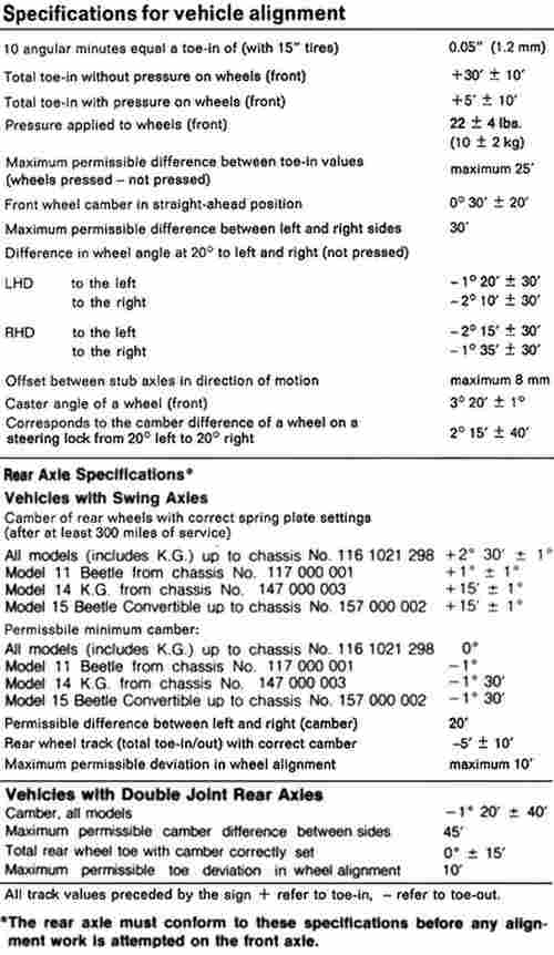
djkeev wrote:A few more helpful pages of Info.
If you want higher resolution copies, email me.
Dave


Hot, humid air is less dense than cooler, drier air. This can allow a golf ball to fly through the air with greater ease, as there won't be as much resistance on the ball.
-
Dale M.

- Posts: 1673
- Joined: Mon Oct 05, 2009 8:09 am
Re: Link Pin Shim Chart

"Fear The Government That Wants To Take Your Guns" - Thomas Jefferson
1970 "Kellison Sand Piper Roadster"
1970 "Kellison Sand Piper Roadster"
-
baja5

- Posts: 2615
- Joined: Thu Aug 10, 2006 1:22 pm
-
ronholm

- Posts: 191
- Joined: Mon Mar 22, 2010 4:59 pm
Re: Link Pin Shim Chart
Thanks a bunch.. that is either tomorrow or the day afters project.. impeccable timing.. 
You just saved me some time for sure...
You just saved me some time for sure...
-
david58
- Moderator
- Posts: 14101
- Joined: Sun Oct 23, 2005 6:14 pm
Re: Link Pin Shim Chart
How can you tell which chart to go by, if you don't know what year the spindles and arms are?
Hot, humid air is less dense than cooler, drier air. This can allow a golf ball to fly through the air with greater ease, as there won't be as much resistance on the ball.
-
Leatherneck
- Moderator
- Posts: 17104
- Joined: Sat Jul 01, 2006 6:47 pm
Re: Link Pin Shim Chart
Count the shims, if you don't have the shims then..... MARC!!!!!!!!!
-
Marc
- Moderator
- Posts: 23741
- Joined: Thu May 23, 2002 12:01 am
Re: Link Pin Shim Chart
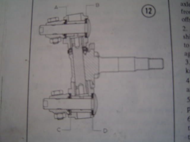
The ends of the later-style (8-shim) control arms have a divot to index the dust seal, while the earlier arms (10-shim) do not.
Note that the dust seal thickess is equivalent to that of two shims at the "A" and "C" locations - the two charts are the same once you make that allowance, indicating that there's no difference in the link-carrier dimensions.
When this change was made (in March of 1960) the outer control arm bushings in the beam were changed to needle bearings. The diameter of the control arms was increased slightly, too, making it inadvisable to mix & match early and late parts. Early arms measured 36.93-36.95mm at the bushing/bearing surface, late arms are 36.98-37.00mm.
-
david58
- Moderator
- Posts: 14101
- Joined: Sun Oct 23, 2005 6:14 pm
Re: Link Pin Shim Chart
Dust seals what dust seals? Do you have pics? By control arms do you mean trailing arms?Marc wrote:The ends of the later-style (8-shim) control arms have a divot to index the dust seal, while the earlier arms (10-shim) do not.
Note that the dust seal thickess is equivalent to that of two shims at the "A" and "C" locations - the two charts are the same once you make that allowance, indicating that there's no difference in the link-carrier dimensions.
When this change was made (in March of 1960) the outer control arm bushings in the beam were changed to needle bearings. The diameter of the control arms was increased slightly, too, making it inadvisable to mix & match early and late parts. Early arms measured 36.93-36.95mm at the bushing/bearing surface, late arms are 36.98-37.00mm.
Hot, humid air is less dense than cooler, drier air. This can allow a golf ball to fly through the air with greater ease, as there won't be as much resistance on the ball.
-
Marc
- Moderator
- Posts: 23741
- Joined: Thu May 23, 2002 12:01 am
Re: Link Pin Shim Chart
They go at "A" and "C" on the later-type front ends...just a little cap that goes on before the shim stack.
Yes, I mean trailing arms.
Yes, I mean trailing arms.
-
Leatherneck
- Moderator
- Posts: 17104
- Joined: Sat Jul 01, 2006 6:47 pm
Re: Link Pin Shim Chart
Bump, good info. Anybody have anything to add?