my stock 1600 dp turbo build!
Posted: Sat Feb 18, 2012 2:10 pm
right trying to do this cheap as possible! most of this is coppied from my local forum so sorry if some of it dont make much sense! also some of it is now well out of date.
here goes........
HERE IS THE TECHNICAL PART....
so here goes 1585cc @ 10psi @ 4500rpm
10 (psi) + 14.7 = 27.4
27.4 / 14.7 = 1.6802
1.6802 is my pressure ratio.
1585(cc) / 16.387 = 96.72301
96.72301 in my engine size in cubic inches
80% on the chart means 1.4 density ratio.
(0.5 x 96.72301 x 4500 (max rpm)) /1728 = 125.9414
125.9414 x 0.8 x 1.6 = 161.20502
161.20502 in my CFM (cubic feet per min)
161.20502 x 0.07 = 11.2843514
11.2843514 is my pounds of are per minute.
so using the density ratio and the lb per min i found a map the put my two figures where they need to be....
in the centremost island on the map!
here it is
garret gt15
found one brand new on ebay for just over £50!
they run them on a 17 tdi astras!!
here she is!
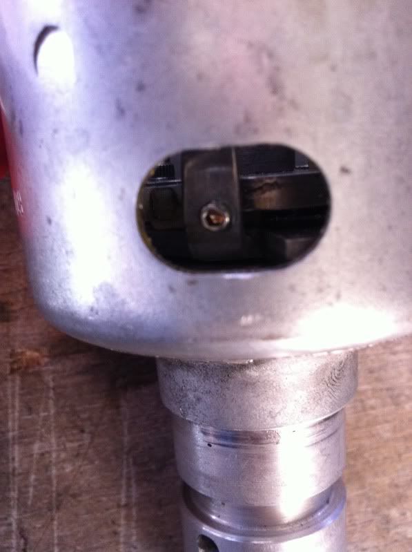
and here is my rev limiter!
4800rpm but i have been told they can be adjusted a little so i can get it to my target 4500rpm
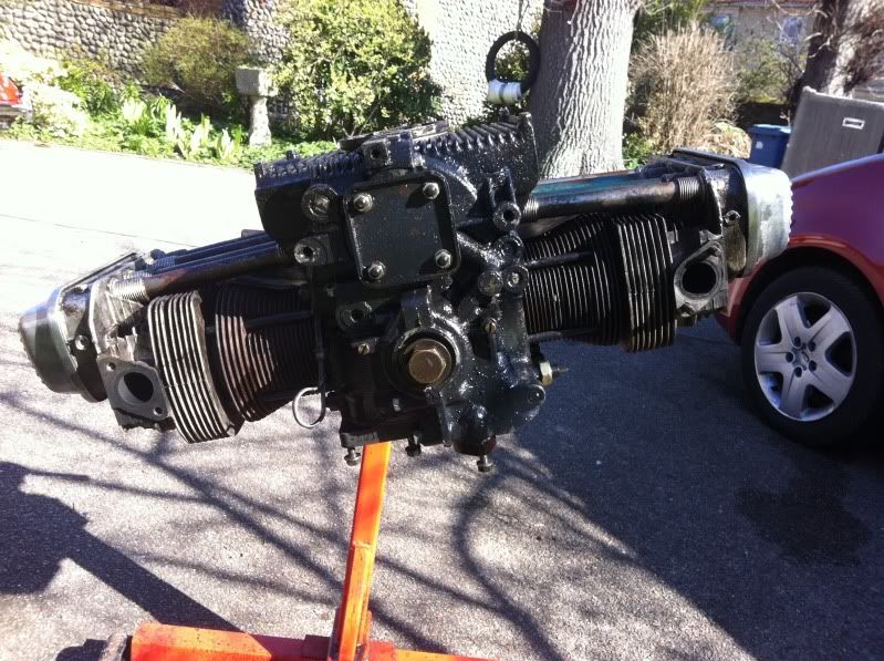
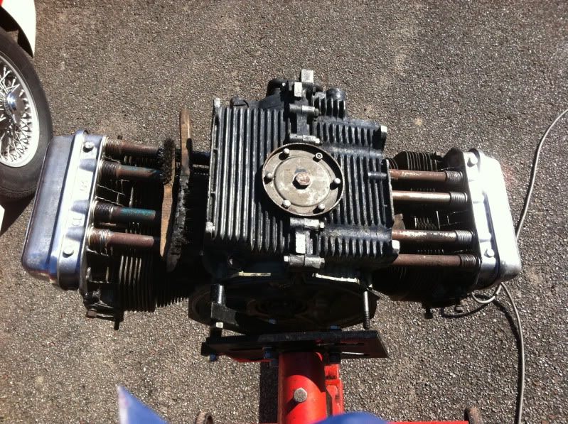
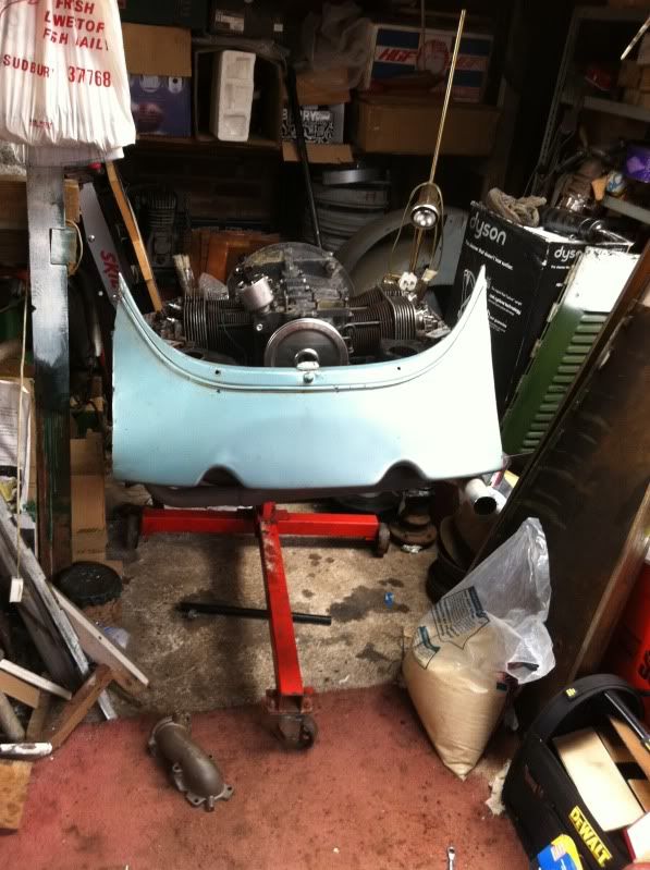
cut off the rear apron and removed the engine for a strip down.
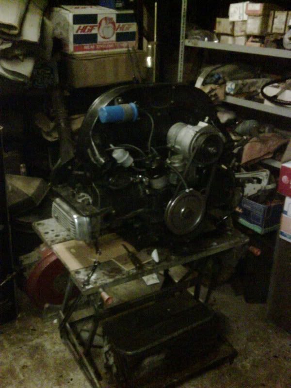
without the rear apron on it took about half hour to remove the engine and under an hour to strip it back to how it is now!
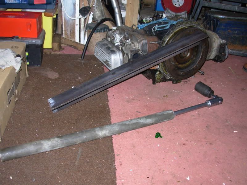
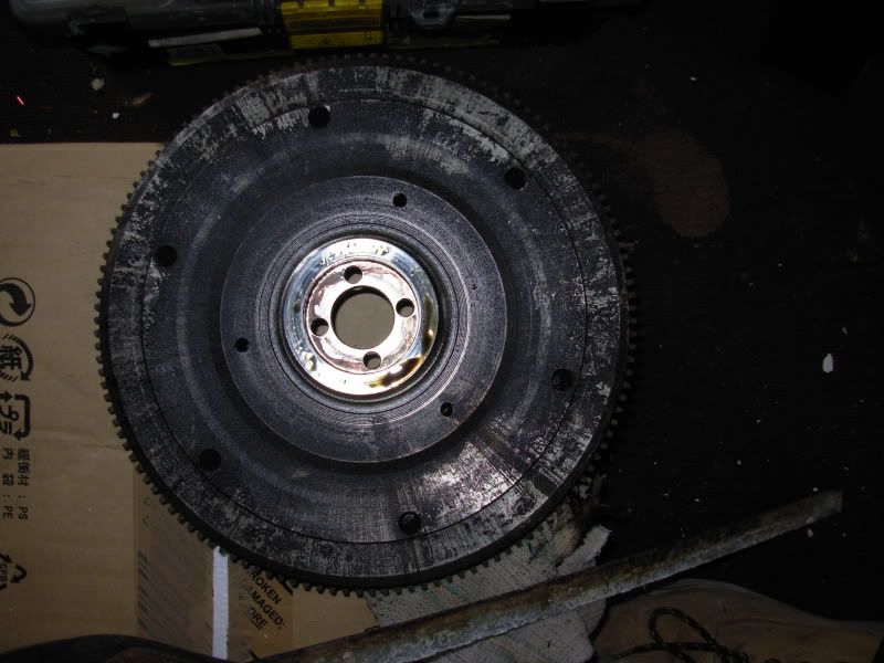
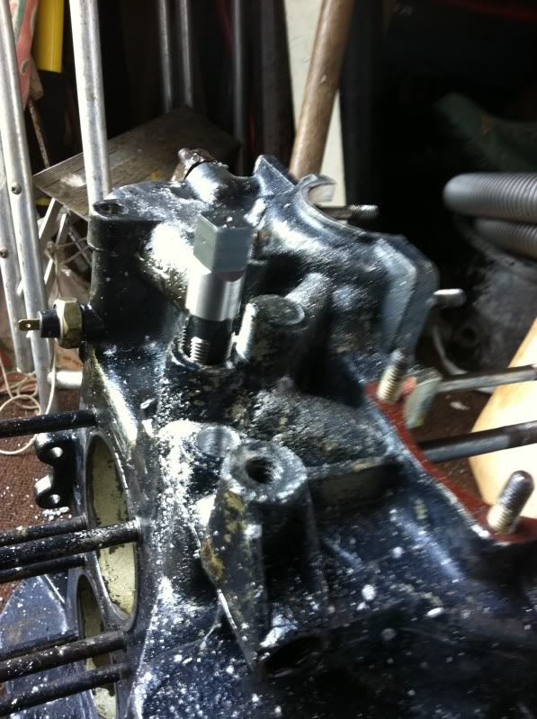
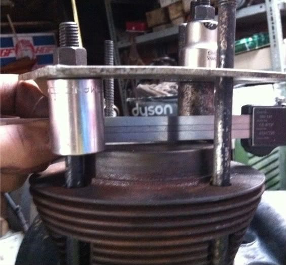
thanks to a few favours from my friend jon and one of his friends, jons brother in law spaner, my grandad and his friend gary who done the welding i finally got the flywheel off. it took around 400 ft/lb at a guess in the end. here's what it took to get it off.
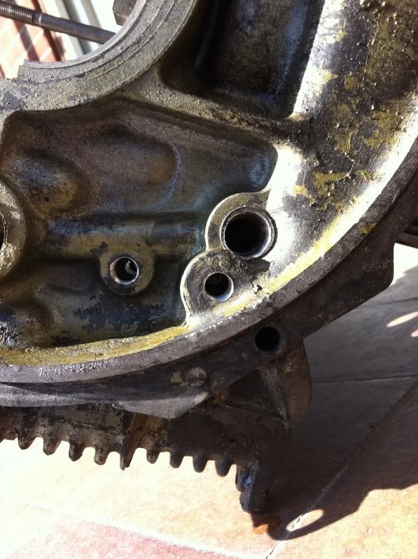
found out where some of the oil was being lost

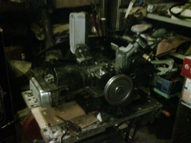
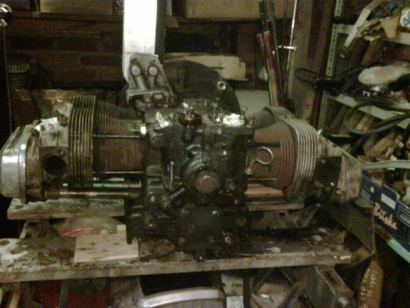
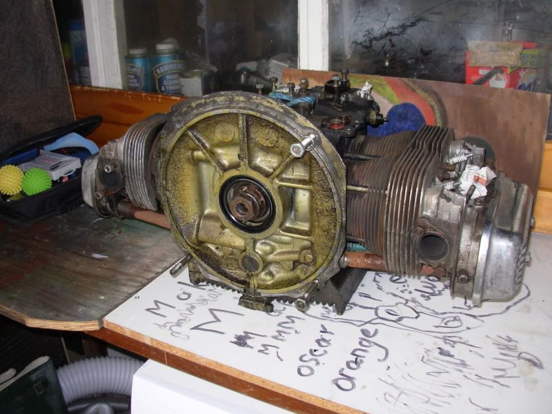
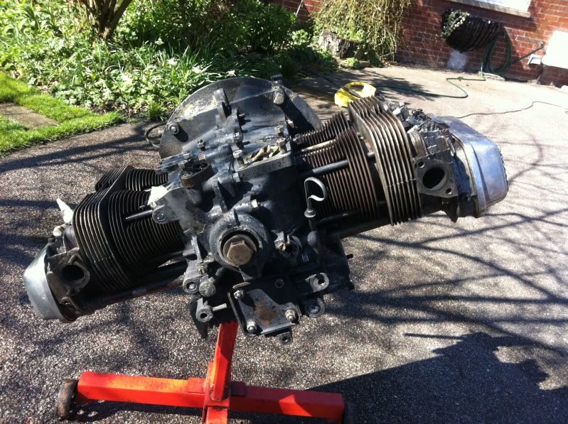
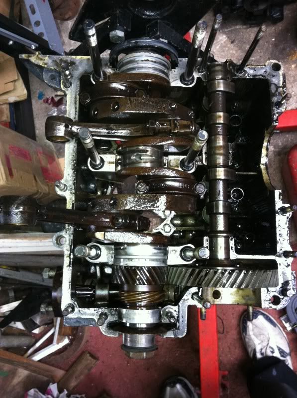
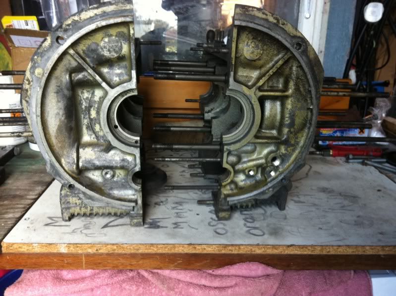
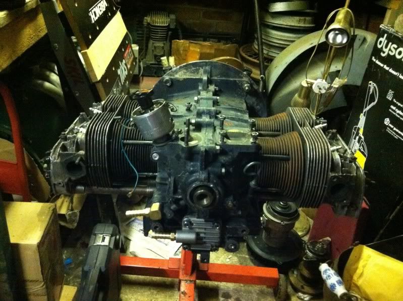
now its off i've got it on the bench ready to pull it apart right down to the crank!
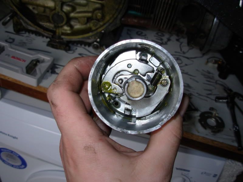
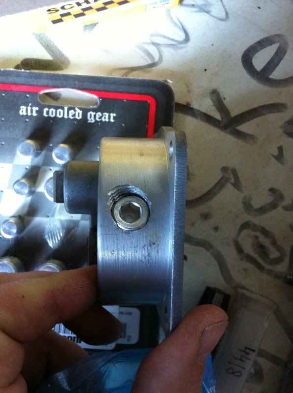
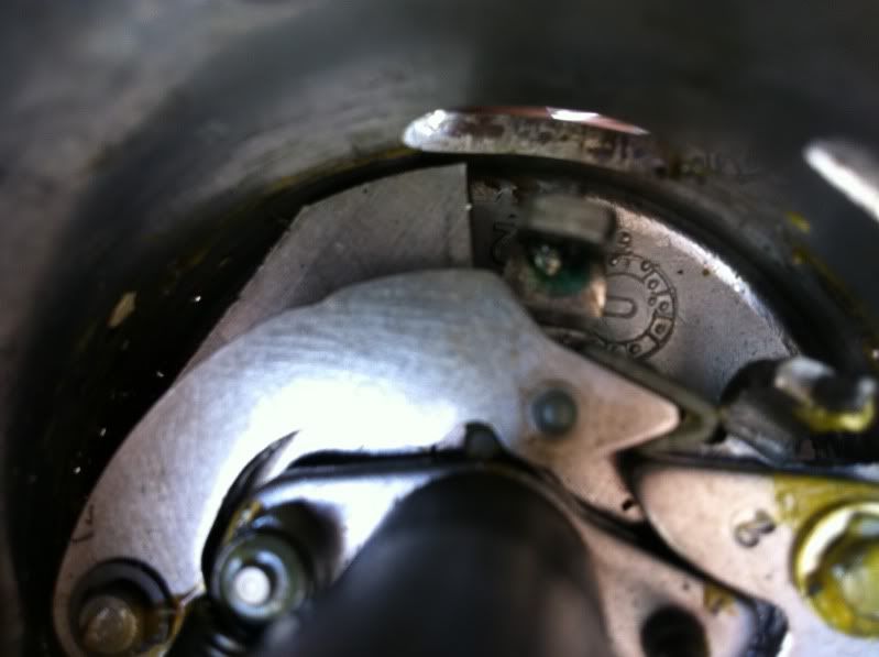
while i was there i stripped back the 009 dizzy to have a look at locking the timing down.
when you at boost and centrifugal advance system without locking it back it will just plain blow up!
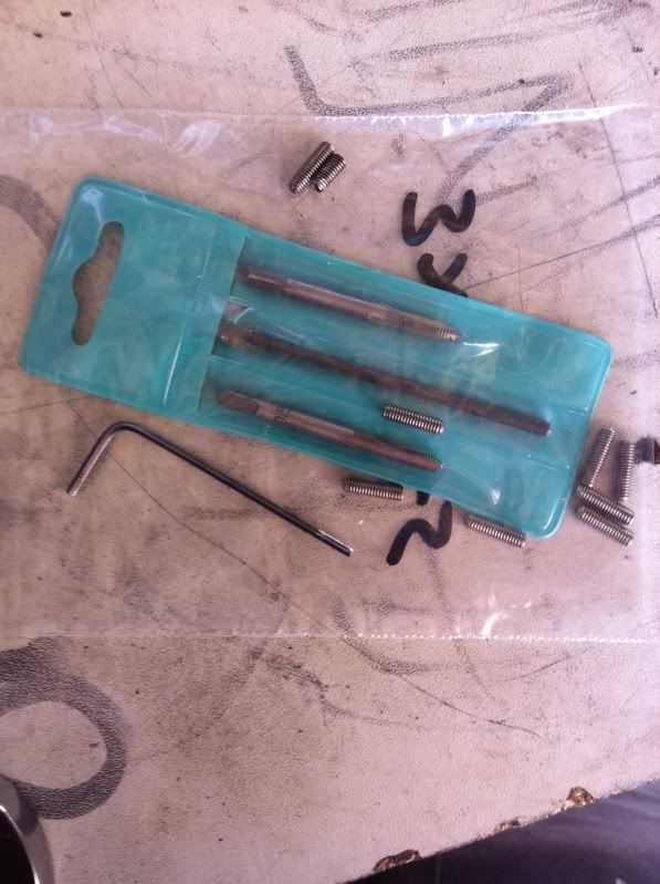
it involves locking the total centrifugal advance down to 7 degrees by drilling and tapping a tab then fitting an M3 grub screw.
have a look here for further info http://www.volkszone.com/VZi/showthread.php?t=395047" onclick="window.open(this.href);return false;" onclick="window.open(this.href);return false;" onclick="window.open(this.href);return false;" onclick="window.open(this.href);return false;
cant remember if i said or not but i got a renault 5 carb, a bailey dump valve and 2" wider front and 4" wider rear fibreglass wings off ebay nice and cheap.
thats it for now but fingers crossed now its on the bench i can get going!
right just a quickie. cleaned the engine for tear down.
before


after
also sorted out some shelves in the garage to top all my parts on to keep things neat and tidy
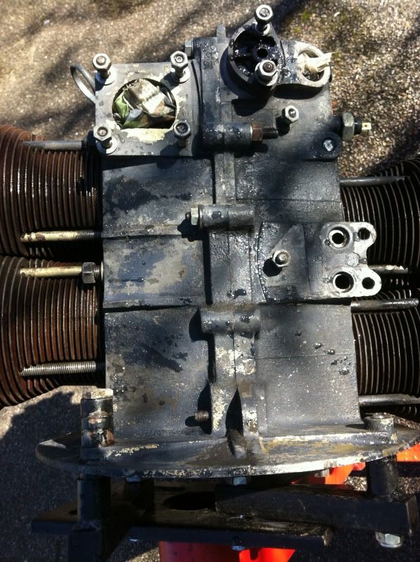
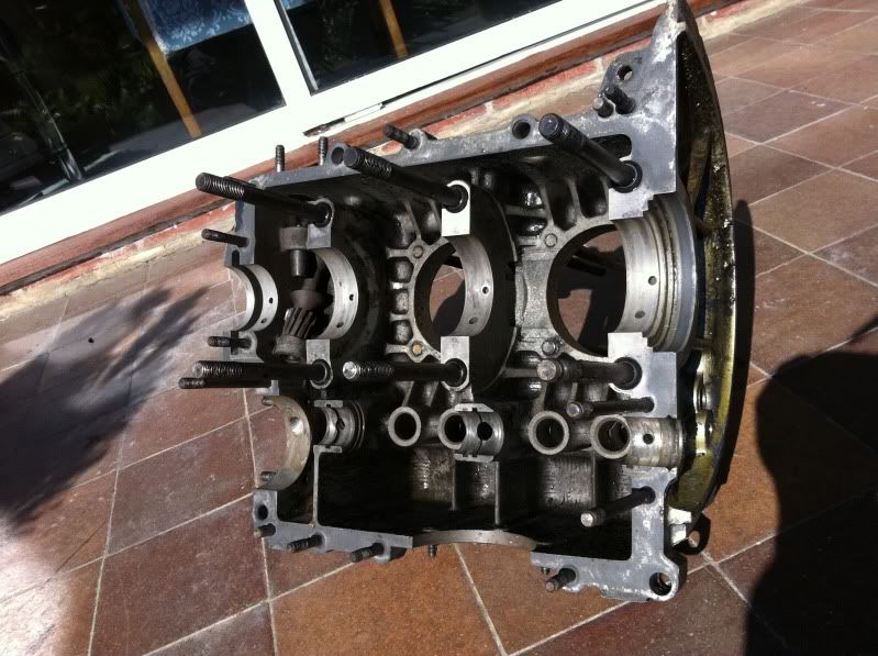
split the case down, and broke the oil pump in the process,
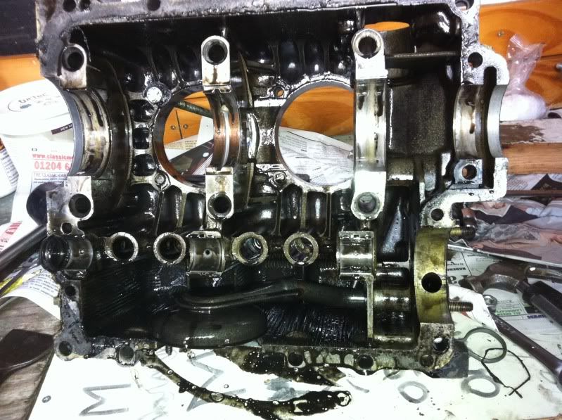
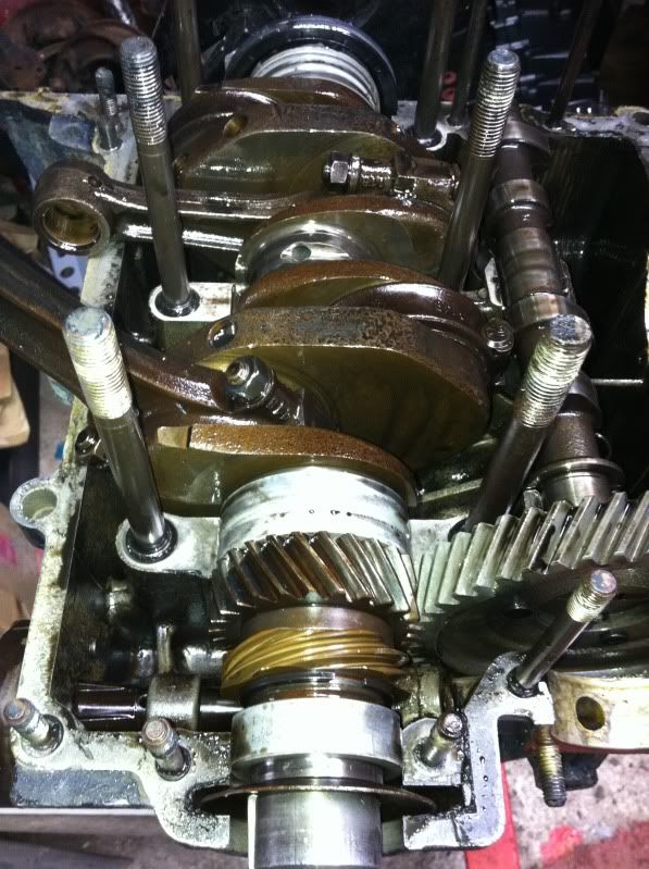
checked everything for wear tolerances, all fine
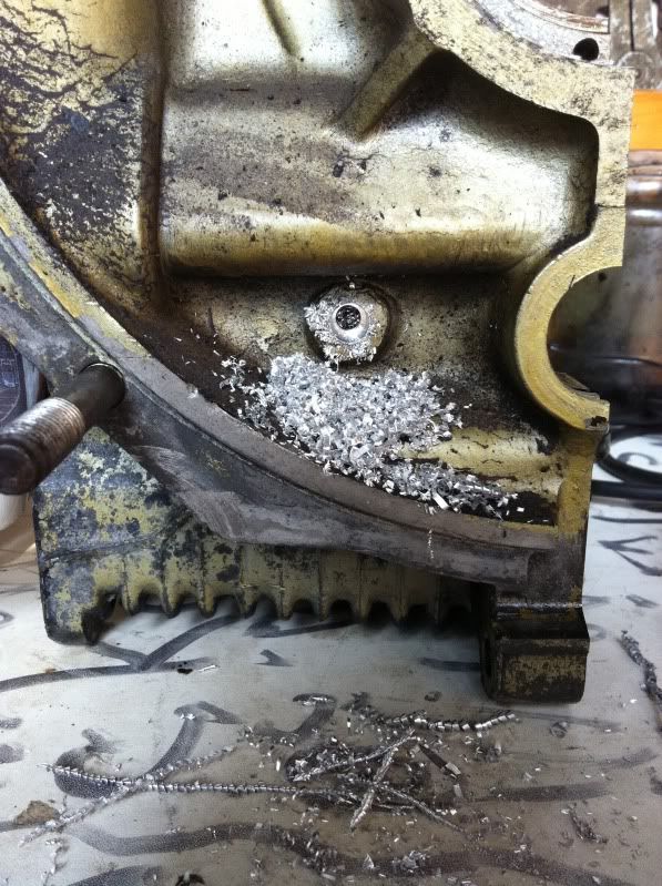
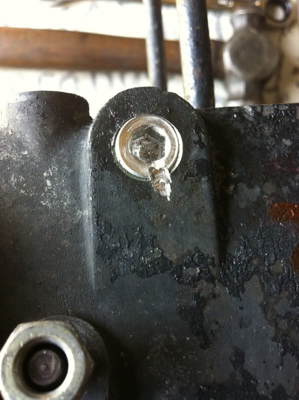
drilled and tapped the oil galleries and oil pump
cleaned out the galleries and cleaned the case again,
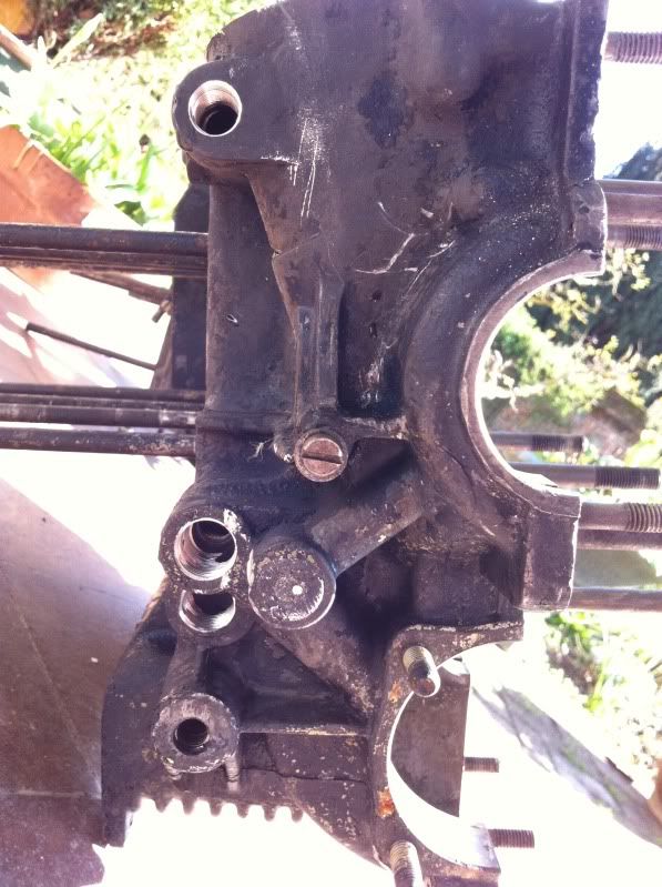
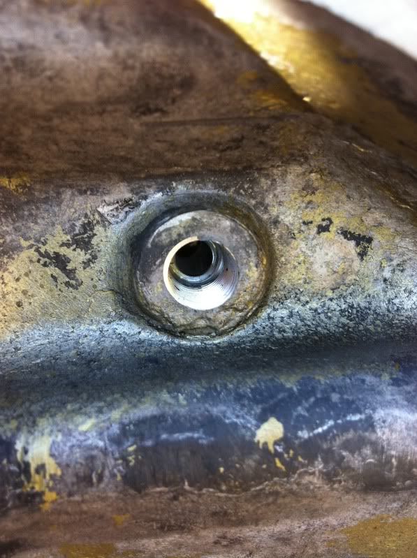
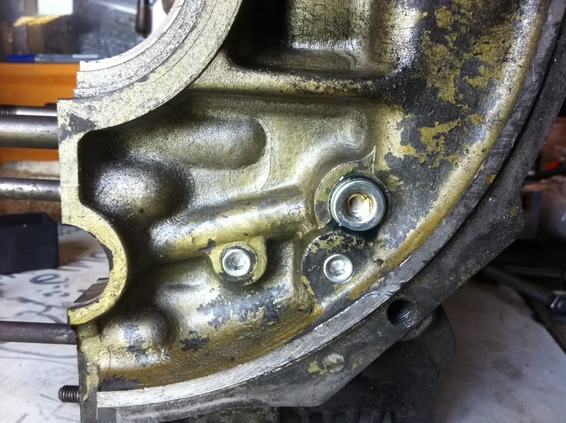
fitted the full flow adaptor and plugs
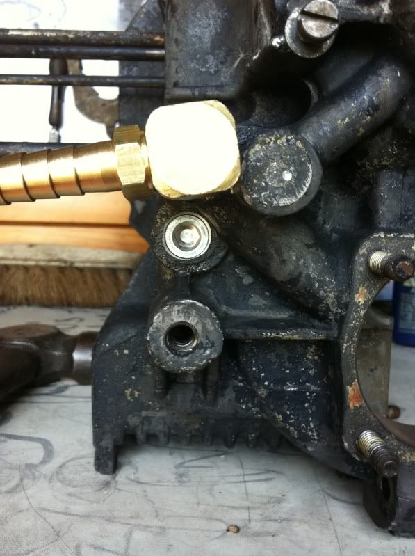
plugged the oil pump
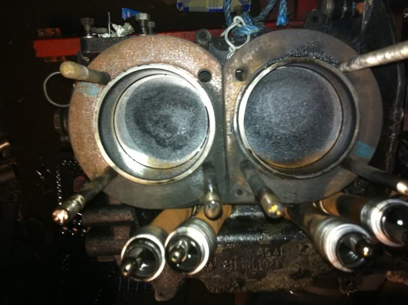
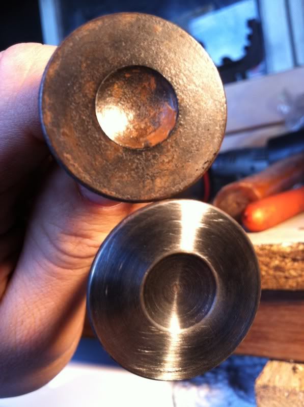
cleaned the piston, heads and valves
before

after
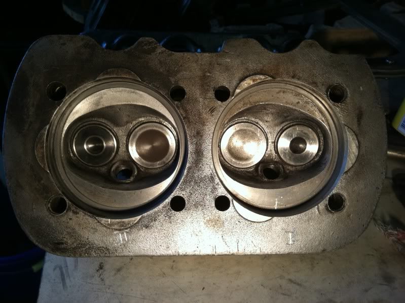
cc'ed and worked the heads to get them all to 49cc, measured and adjusted deck height from .060" to .070" to lower the compression,
modified the 009 dizzy so it will only advance 7*,
lapped all the valves
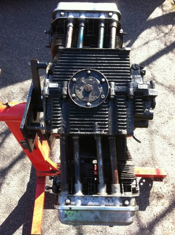
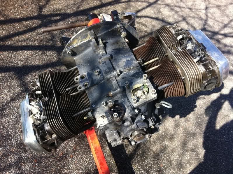
refitted the internals and sealed the case, fitted the dizzy,

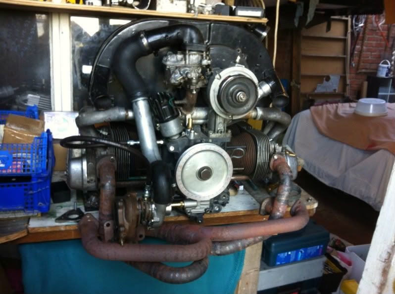
this is how i left it tonight, nearly ready to think about the pipework for the turbo!!
compression ratio is now set at 7.7:1 so i should be ok to run 1bar of boost or roughly 15psi but for now will aim for 10psi and maybe build up from there slowly.
tomorrow i want to set up the valves, rockers arms and static timing. Them Saturday think about test fitting it to the car to see what space i have to mount the turbo, fingers crossed!
had a few hours in the garage yesterday and clocked the turbo again, pretty much back to where it was in the beginning!
found somewhere where it would fit, where the oil would drain back ok, where the inlet and outlet would fit ok and where it would fit under the car itself.
to save the hassle of taking the engine to the car i took the part of the car i need to the engine
i got one of there for £15 including j tubes at elemental!!
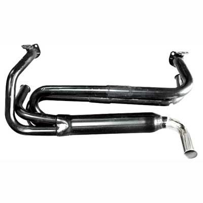
thought if i chopped it up it might be cheaper than the £300+ the cb performance headers are!
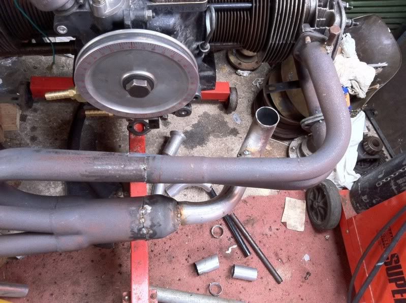
so i started to chop it about....
cut out a section of the 3" exhaust, removed the baffle,
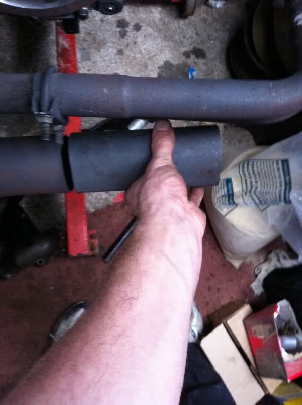
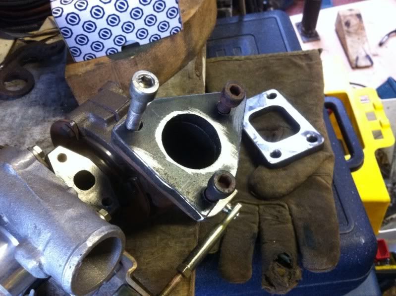
cut off the reducing tip (3" to 1 5/8"), this is where i'll weld it back on, the 90* bend will get cut off and a 35* will take its place, the 90 will then have a flange put on and join to the turbo,
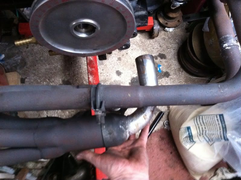
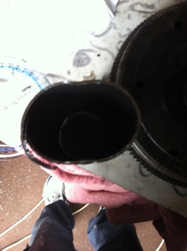
as luck would have it squashed the section of 3" down to oval in a vice and it will fit perfectly as an outlet for the turbo
thats it for now!
still got loads to do, but its getting there slowly
so here goes again.........
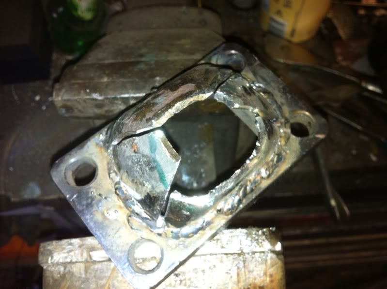
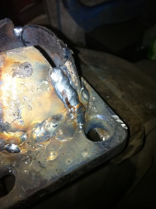
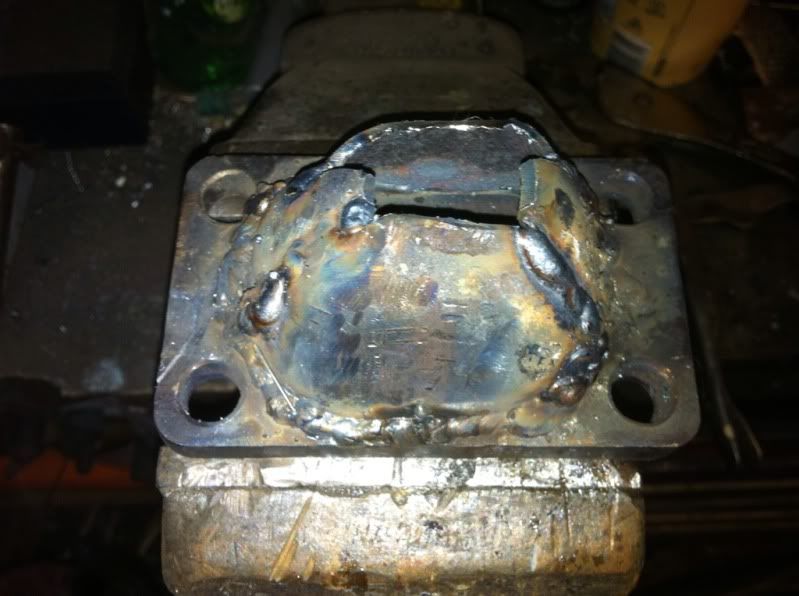
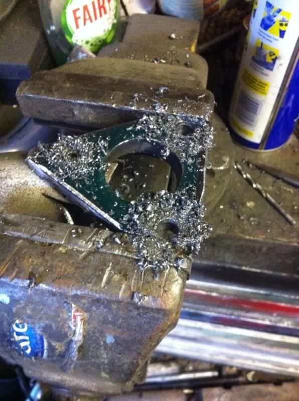
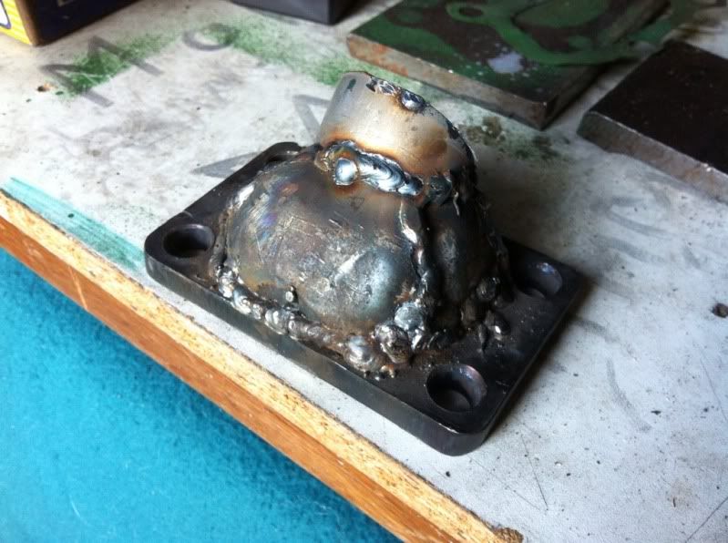
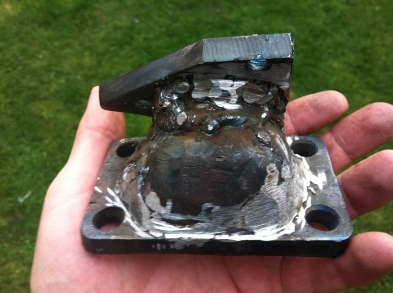
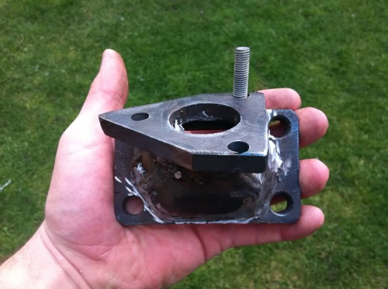
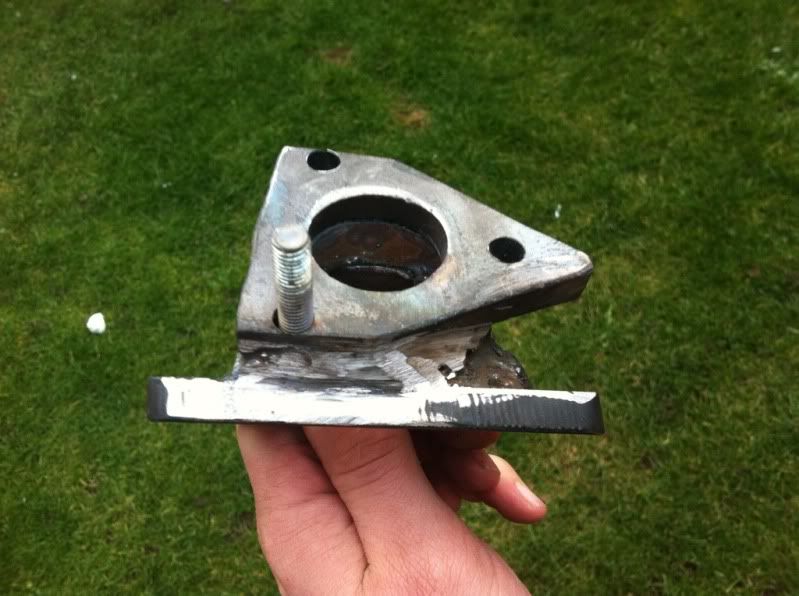
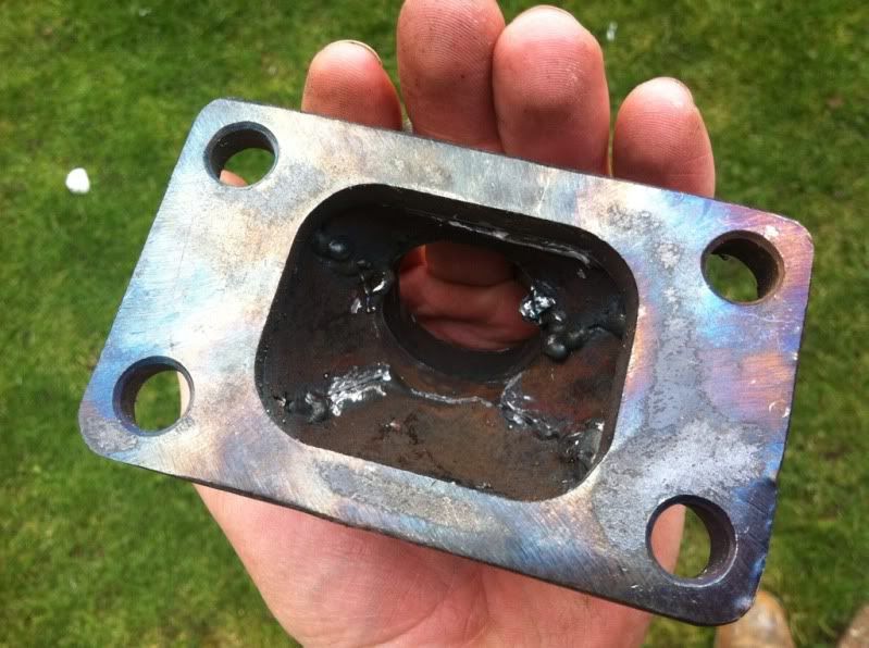
my first go at welding stuff that matters!
filled the pre heater holes as they're no longer needed,
offering up the parts and weldong to get the turbo where i want it to sit


yeah its ugly and not 100% perfect but chopping this old exhaust was around £285 cheaper than buying one
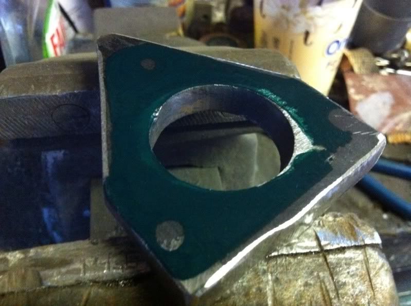
need to get it gas tight, get the gt15 flange made up blah blah blah!
y'all are up to date!
Right folks a little update. After the wedding and Xmas etc I've now got the time and money to get a little bit done to the bug.
I found a cb performance turbo header for sale so I've ditched my old set up and gone with that! Here it is half mocked up. As my turbo is a gt1544 I need to sort out a flange adaptor and remove the wastegate. I have just this morning bought an external 38mm wastegate to fit to the exhaust also.
here goes........
HERE IS THE TECHNICAL PART....
[color=#FF0000]scott the viking wrote[/color] wrote:
I have been trying to figure out a very simple way to put this...I think can make it understandable...but not simple. Actually....a novel could be written on turbo selection because all of the different variables involved. SO...I will cover what a compressor map is for and what roll it plays in selection. There will still be a lot of unanswered questions...so feel free to ask about anything you don't fully understand.
Alright...for this I will use an engine I just put together for my rail, because it is still fresh in my mind. This is probably a little larger CC than most of you in here are used to messing with....but the formula can be used for any size CC...bigger or smaller. So lets get started........
Like I mentioned before...there is more to this and also different ways to do it...but this example will be based on engine CFM (cubic feet per minute) I am sure that most of you have heard CFM discussed before...probably when someone was talking about a carb on a V8. What I am going to do here is show you how to figure how much CFM your engine will need...which will help you read maps when looking for a turbo.
To do this you will need to know the following...The size of your engine, the maximum amount of boost you will run and the maximum RPM your engine will be turned to. So in example
Engine size 2387cc
Max boost 15 psi
Max RPM 6000
With this info, we can figure out what is referred to as a pressure ratio and this is done just like so.... Boost pressure (15psi) + atmospheric pressure (14.7 at sea level)...divided by 14.7......
15+14.7 =29.7............................................. 29.7/14.7=2.02.
Therefore....2.02 is your pressure ratio.
Next step in figuring the CFM your engine will require........ I mostly work with V8's...so it is easier for me to turn CC's into cubic inches...To do that, you divide your engine's cc by 16.387.............2387/16.387=145. So I am now dealing with a 145 cubic inch engine.
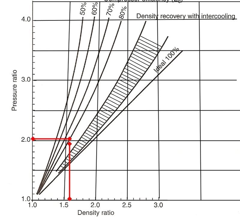
To find the amount of air that this turbo charged engine will use we will multiply the engine's volumetric efficacy (or V.E) by a density ratio (told you this was not simple) We will call the V.E of a turbo vw 80%...NOW to find the density ratio. I want you guys to keep in mind that there are A LOT of different ways to figure these things....and I am trying to keep as little of math involved with this explanation as I can...but the fact is...it just can't be explained without a little....Anyway...instead of going into how to figure density...We will use this graph. I am sure there are some better ones...but this is all I could whip up at the moment.
So we know that the pressure ratio is at 2.02... We go up the side of the graph marked pressure ratio until we hit 2.02. Then we "feel" that the engine is running 80% V.E. We slide our finger over to 80%, then we go straight down to the bottom marked density ratio, and you will see that you have about a 1.60 density ratio. I know that non of this means squat right now...but it will all kind of tie together at the end.
We now have enough information to start the equations to figure CFM needed...and that goes something like this....
0.5Xcubic inchXmaximum RPM, divided by 1728 X VE.XDR. and that will equal your CFM.......so.........
0.5 x 145 x 6000=435000 ............Divide that by 1728 and that comes to roughly 251. Now take that and do this...
251 x .80 (ve) x 1.60 (d.r) and that will come out to 321.28....and that is your CFM.
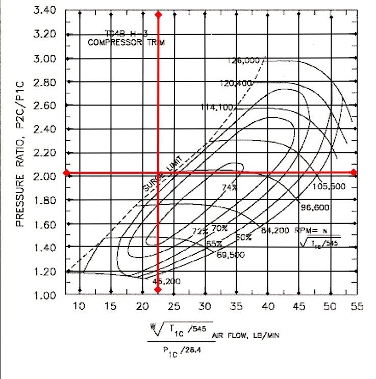
WOW...we are almost ready to start looking at turbo maps. We have a pressure ratio of 2.02 and a turbocharged airflow of 321.28 CFM. Just one more thing with the CFM...."most" of the guys that make up turbo maps do so with the bottom part in "pounds of air" not CFM....So you need to convert your CFM into pounds of air... The way you do that is you take your CFM 321.28 and multiply it by 0.070 and that will come out to pounds of air per minute...321.28x0.070= 22.4896.
Let's just skip the long number for this demo and call it 22.5 pounds of air. This explanation is already way too long winded...So I am going to skip what all the little islands and lines on this compressor map mean. What I will tell you is this....See that line on the left of the chart? That is called a "surge line" You will see from the red lines I made on this map...(one of them going to our pounds of air, one going to our pressure ratio) Where those lines intersect is how well your engine will work with this turbo compressor. You see it falls to the left of the surge line....this is no good...this is not the turbo for the engine combination the we want to run. When you get beyond the left of that surge line...that is where the flow and the pressure of the compressor are out of whack. They cavitate, sound like a slush pump, spin like wild, etc. Every hear a powerstroke Ford truck running slow and it sounds like it's exhaust is running under water? Then you listen to a Dodge Cummins and it's just a nice smooth whistle? That's the Ford surging and the Cummins running like it should.
See the percentage numbers on the map? That is how efficiently the compressor "can" work. Ideally, you want to pick a compressor set-up for your engine, where those two red lines will intersect at the highest compressor efficiency (high percent number).
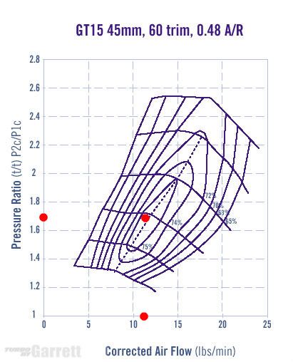
so here goes 1585cc @ 10psi @ 4500rpm
10 (psi) + 14.7 = 27.4
27.4 / 14.7 = 1.6802
1.6802 is my pressure ratio.
1585(cc) / 16.387 = 96.72301
96.72301 in my engine size in cubic inches
80% on the chart means 1.4 density ratio.
(0.5 x 96.72301 x 4500 (max rpm)) /1728 = 125.9414
125.9414 x 0.8 x 1.6 = 161.20502
161.20502 in my CFM (cubic feet per min)
161.20502 x 0.07 = 11.2843514
11.2843514 is my pounds of are per minute.
so using the density ratio and the lb per min i found a map the put my two figures where they need to be....
in the centremost island on the map!
here it is
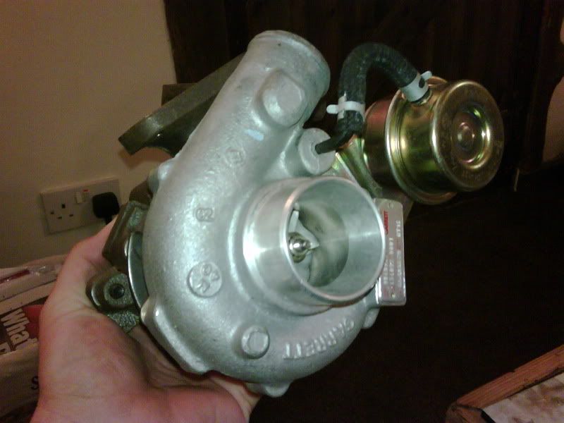
garret gt15
found one brand new on ebay for just over £50!
they run them on a 17 tdi astras!!
here she is!
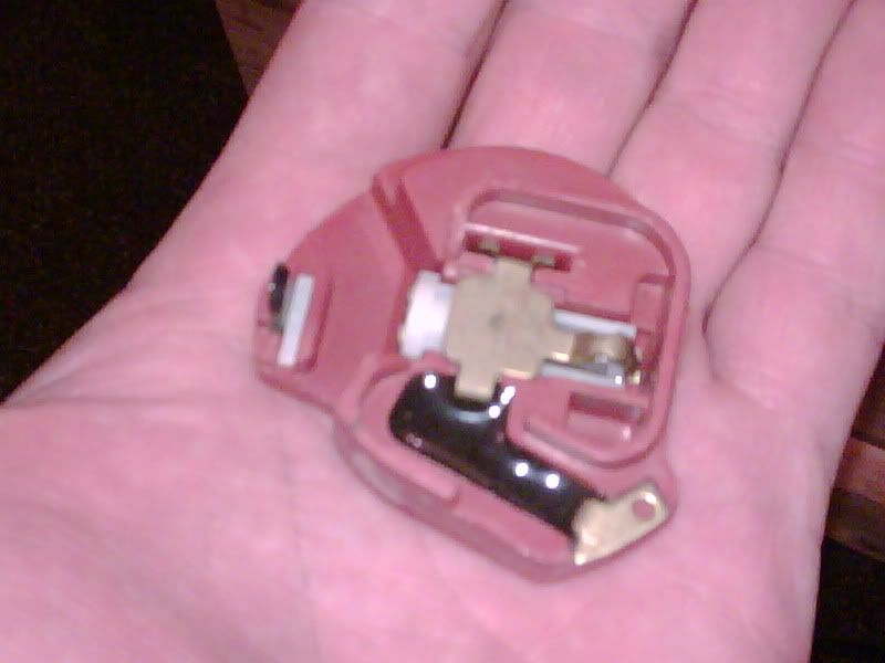
and here is my rev limiter!
4800rpm but i have been told they can be adjusted a little so i can get it to my target 4500rpm
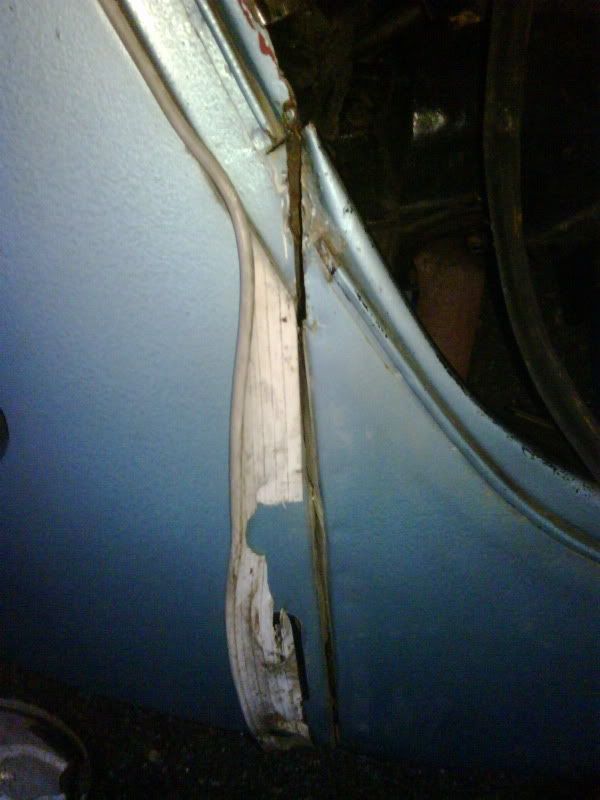
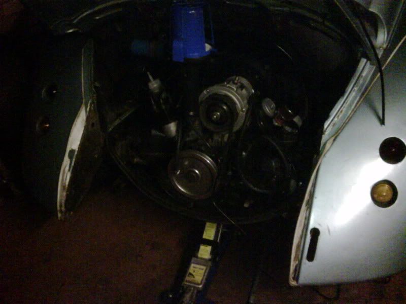
cut off the rear apron and removed the engine for a strip down.
without the rear apron on it took about half hour to remove the engine and under an hour to strip it back to how it is now!
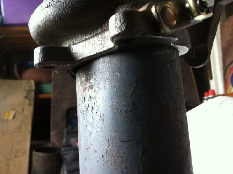
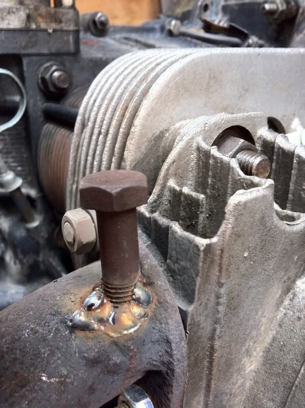
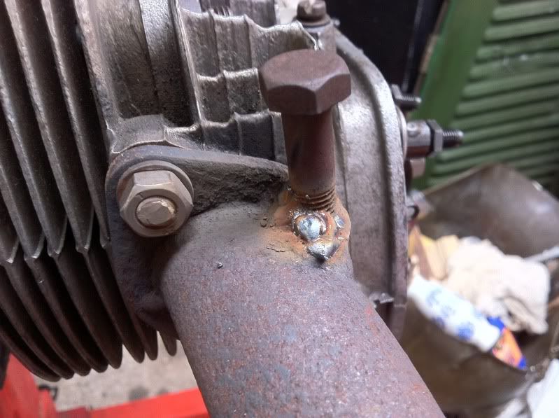
thanks to a few favours from my friend jon and one of his friends, jons brother in law spaner, my grandad and his friend gary who done the welding i finally got the flywheel off. it took around 400 ft/lb at a guess in the end. here's what it took to get it off.
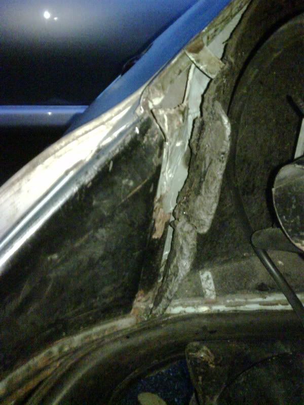
found out where some of the oil was being lost
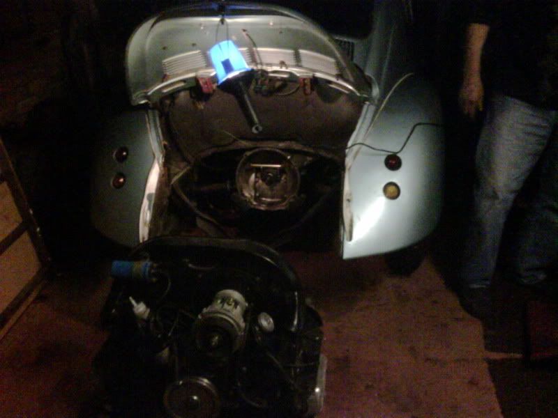
now its off i've got it on the bench ready to pull it apart right down to the crank!
while i was there i stripped back the 009 dizzy to have a look at locking the timing down.
when you at boost and centrifugal advance system without locking it back it will just plain blow up!
it involves locking the total centrifugal advance down to 7 degrees by drilling and tapping a tab then fitting an M3 grub screw.
have a look here for further info http://www.volkszone.com/VZi/showthread.php?t=395047" onclick="window.open(this.href);return false;" onclick="window.open(this.href);return false;" onclick="window.open(this.href);return false;" onclick="window.open(this.href);return false;
cant remember if i said or not but i got a renault 5 carb, a bailey dump valve and 2" wider front and 4" wider rear fibreglass wings off ebay nice and cheap.
thats it for now but fingers crossed now its on the bench i can get going!
right just a quickie. cleaned the engine for tear down.
before
after
also sorted out some shelves in the garage to top all my parts on to keep things neat and tidy
split the case down, and broke the oil pump in the process,
checked everything for wear tolerances, all fine
drilled and tapped the oil galleries and oil pump
cleaned out the galleries and cleaned the case again,
fitted the full flow adaptor and plugs
plugged the oil pump
cleaned the piston, heads and valves
before
after
cc'ed and worked the heads to get them all to 49cc, measured and adjusted deck height from .060" to .070" to lower the compression,
modified the 009 dizzy so it will only advance 7*,
lapped all the valves
refitted the internals and sealed the case, fitted the dizzy,
this is how i left it tonight, nearly ready to think about the pipework for the turbo!!
compression ratio is now set at 7.7:1 so i should be ok to run 1bar of boost or roughly 15psi but for now will aim for 10psi and maybe build up from there slowly.
tomorrow i want to set up the valves, rockers arms and static timing. Them Saturday think about test fitting it to the car to see what space i have to mount the turbo, fingers crossed!
had a few hours in the garage yesterday and clocked the turbo again, pretty much back to where it was in the beginning!
found somewhere where it would fit, where the oil would drain back ok, where the inlet and outlet would fit ok and where it would fit under the car itself.
to save the hassle of taking the engine to the car i took the part of the car i need to the engine
i got one of there for £15 including j tubes at elemental!!
thought if i chopped it up it might be cheaper than the £300+ the cb performance headers are!
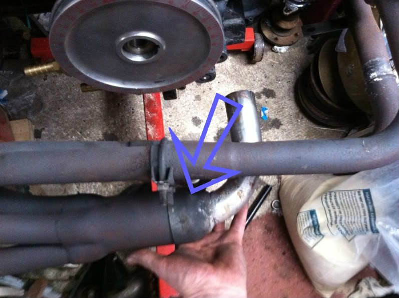
so i started to chop it about....
cut out a section of the 3" exhaust, removed the baffle,
cut off the reducing tip (3" to 1 5/8"), this is where i'll weld it back on, the 90* bend will get cut off and a 35* will take its place, the 90 will then have a flange put on and join to the turbo,
as luck would have it squashed the section of 3" down to oval in a vice and it will fit perfectly as an outlet for the turbo
thats it for now!
still got loads to do, but its getting there slowly
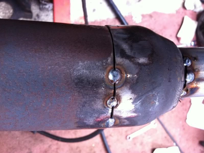
so here goes again.........
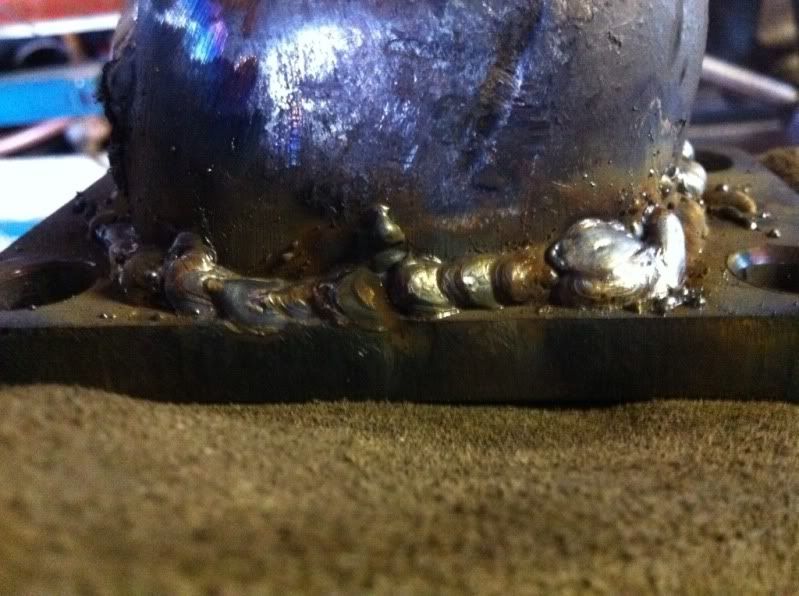
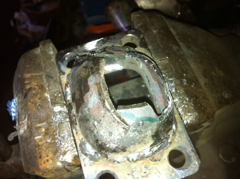
my first go at welding stuff that matters!
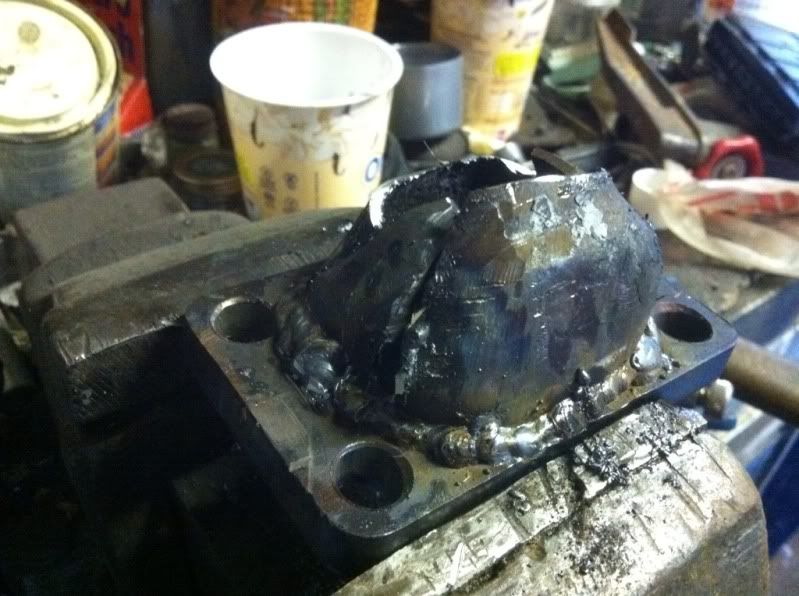
filled the pre heater holes as they're no longer needed,
offering up the parts and weldong to get the turbo where i want it to sit
yeah its ugly and not 100% perfect but chopping this old exhaust was around £285 cheaper than buying one
need to get it gas tight, get the gt15 flange made up blah blah blah!
y'all are up to date!
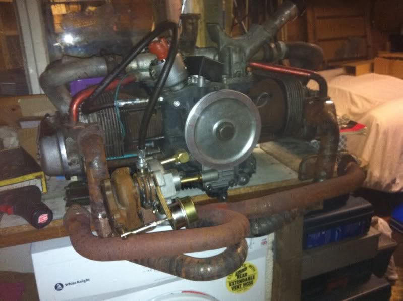
Right folks a little update. After the wedding and Xmas etc I've now got the time and money to get a little bit done to the bug.
I found a cb performance turbo header for sale so I've ditched my old set up and gone with that! Here it is half mocked up. As my turbo is a gt1544 I need to sort out a flange adaptor and remove the wastegate. I have just this morning bought an external 38mm wastegate to fit to the exhaust also.