I was testing a new coil when I saw smoke coming from the alternator. I immediately shut it off but the damage must have already been done because after cautiously starting it up again I measured 12v at the batter. So I replaced the alternator and regulator but I'm still getting 12v at the battery.
Any ideas? I've kinda replaced the whole system at this point... The only thing I can think of is maybe one of the parts are DOA but that would make me very sad after all the trouble I went into getting the stupid alt in.
Electrical charging system issue
-
Stray Catalyst
- Posts: 808
- Joined: Sun Sep 20, 2009 4:42 am
Re: Electrical charging system issue
Was your alternator the internally regulated kind? In any case, take it out and bring it to the car parts store - most of them can test it (AFTER you take the fan and associated sheet metal off, which is a pain in the ass) and you can either find the problem or eliminate the alternator as a problem.
If you've rewired the car, make sure you didn't connect the wire from the alt to the wrong terminal on the battery... my worst electrical fire was from that mistake, when the black-with-red 8AWG wire was connected to the negative terminal on the battery. It destroyed the alt, the battery, and the wiring harness from the back seat of the car to the engine compartment.
If you've rewired the car, make sure you didn't connect the wire from the alt to the wrong terminal on the battery... my worst electrical fire was from that mistake, when the black-with-red 8AWG wire was connected to the negative terminal on the battery. It destroyed the alt, the battery, and the wiring harness from the back seat of the car to the engine compartment.
-
foreverska
- Posts: 137
- Joined: Tue Jun 18, 2013 11:24 am
Re: Electrical charging system issue
This system is so screwed up. It's a 70 bug (Oct 69) with a 3pin 73 alt. Then the po took the 3 pin harness and spliced it into a 4 pin connector and used a 4 pin reg.
I didn't think about wiring... but I can see 12v at the alternator connector.
I didn't think about wiring... but I can see 12v at the alternator connector.
-
Marc
- Moderator
- Posts: 23741
- Joined: Thu May 23, 2002 12:01 am
Re: Electrical charging system issue
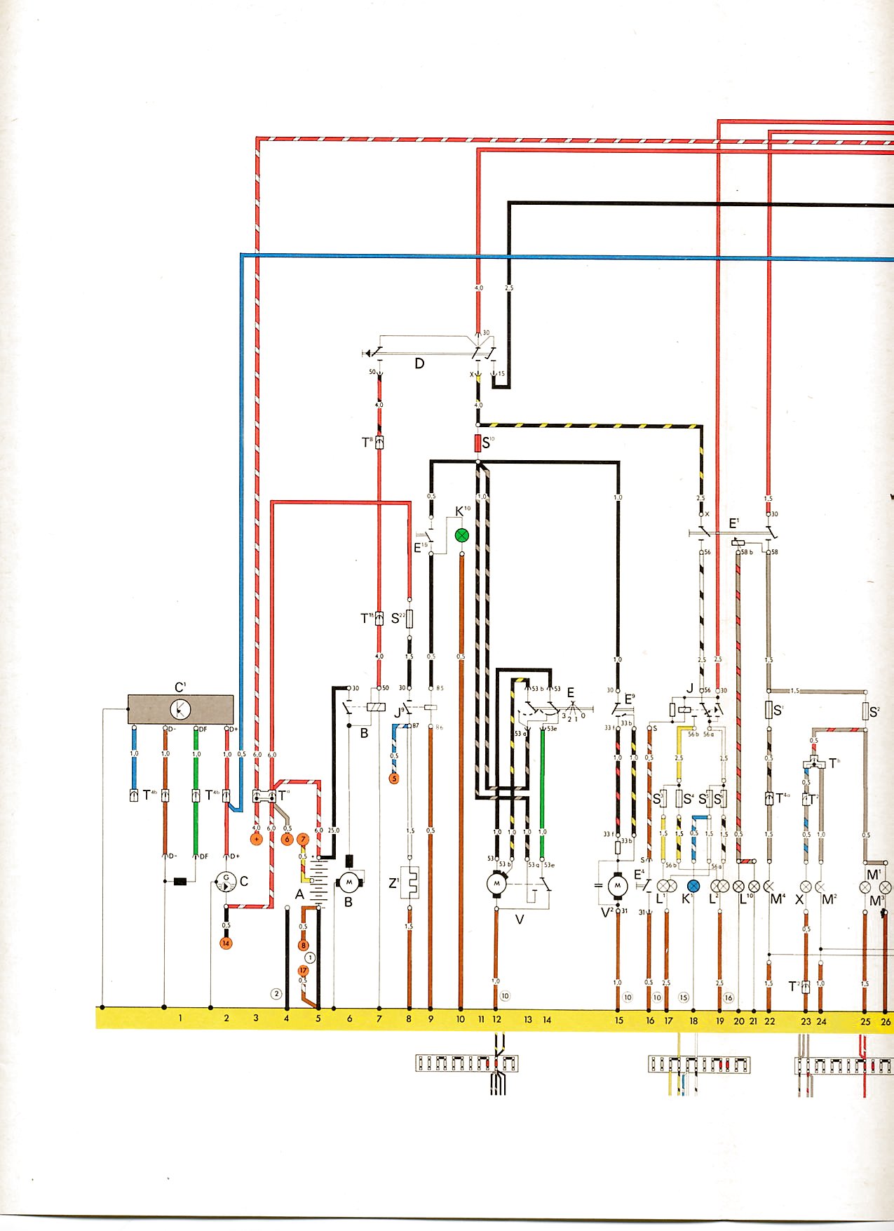
I'm assuming that he tossed the original generator regulator and put in one for an externally-regulated alternator (they have a pigtail with four wires leading to a rectangular white connector).
Note that the blue wire from the external regulator connects to nothing - the Red, Green, and Brown wires from the externally-regulated alternator all connect to the matching color wires from the regulator.
There's a blue wire in the main harness that goes to the warning lamp (true regardless of what generator/alternator the car came with)...it does NOT connect to the blue wire from the regulator as one might expect, it needs to join the red ones.
http://www.vintagebus.com/wiring/1303_f ... 1973-1.jpg
"C" is the alternator, "C1" is the regulator. The wires going to orange circles are for the dealer diagnostic plug and won't exist in your `70; you also won't have white stripes on the big red B+ wires (unless those were updated).
-
foreverska
- Posts: 137
- Joined: Tue Jun 18, 2013 11:24 am
Re: Electrical charging system issue
I found this:
http://www.netlink.net/mp/volks/htm/gen.htm
The new one failed both tests. Back to Autozone with it. Now I have to wait 2 days for a new one.
http://www.netlink.net/mp/volks/htm/gen.htm
The new one failed both tests. Back to Autozone with it. Now I have to wait 2 days for a new one.
-
sideshow

- Posts: 3428
- Joined: Mon Oct 27, 2003 11:00 am
Re: Electrical charging system issue
That test does nothing for an alternator
Yeah some may call it overkill, but you can't have too much overkill.
-
hemicat
- Posts: 167
- Joined: Fri Nov 21, 2008 6:24 pm
Re: Electrical charging system issue
Dumb question, have you checked the charging light to see if it is working in the Speedo? Think I remember reading somewhere that if the light is not working it will not allow the alternator to excite and charge. Could be wrong but something else to check.
-
foreverska
- Posts: 137
- Joined: Tue Jun 18, 2013 11:24 am
Re: Electrical charging system issue
Not even the voltage check between D+ and DF? That was a solid zero.sideshow wrote:That test does nothing for an alternator
I don't thing I've ever seen the alt light work. I guess I can try to fix it though because you're right I did see that said. I kinda dismissed it though because it's never worked for me.
-
hemicat
- Posts: 167
- Joined: Fri Nov 21, 2008 6:24 pm
Re: Electrical charging system issue
Easiest way to check is if the oil light is working try swapping it with the charge. That will let you see if the wiring to the light is good. Quick, simple and cheap... Just how I like them 
-
Marc
- Moderator
- Posts: 23741
- Joined: Thu May 23, 2002 12:01 am
Re: Electrical charging system issue
The externally-regulated alternators have been obsolescent for years - back in 1974 they were superseded by the internally-regulated style, and that's the only type I'd pay money for anymore. Bosch AL82 ("N" or "X" suffix depending upon whether sold as new or rebuilt/exchange). Their wiring is real simple, all you have to do is extend the blue wire from the warning lamp back to the D+ push-on terminal on the alternator.
One other wiring necessity when converting from generator to alternator (either type) is that the big red wires all be bonded together under the back seat. One from the alternator, one to the battery, and one to the front of the car through the main harness. This junction will be "hot" at all times and needs to be well-insulated. Cars which came with alternators from the factory had giant 4-way insulated push-on connectors (the 4th wire was just for the diagnostic plug) but you can improvise, just make a good connection and be sure it's well-protected.
Generators don't care if the warning lamp works or not. They get their initial "field flash" from the residual magnetism present in the substantial amount of ferrous metal in the housing...a generator doesn't ordinarily need polarizing unless it's been sitting idle for months & months; after running it briefly as a motor, enough residual magnetism is again present to get it to "kick off" as a generator.
Alternators are made mostly of aluminum & copper and don't hold their residual magnetic field for long - perhaps a few weeks - so they rely upon the voltage applied from the ignition switch through the filament of the warning lamp to get them started. And sometimes even with the lamp working they may need to be revved up to a couple thousand RPM or more before they get with the program again. As sideshow said, the generator tests do not apply to an alternator, and you could damage it easily if you goof up trying. It's recommended that an alternator never be operated "open circuit" (no battery connected to serve as a reference voltage) because its voltage could possibly spike high enough to damage one of the output diodes.
-
foreverska
- Posts: 137
- Joined: Tue Jun 18, 2013 11:24 am
Re: Electrical charging system issue
Swapped oil and gen wires, gen lights up under batt. Swap 'em back and dead. Pull out the doghouse (easy since I already have the gen out and the decklid off) and take a gander at the wire group headed towards the alt. One wire hanging out by itself but it's kinda greenish. Hook it to the loop on the end of the alt wire and gen light comes on.
I guess that's it but where does it go? Diagrams kinda show it going to the reg somehow but that doesn't make sense in my mind with the 3 pin connector. I have a fat red and and a normal brownish wire that tie together and become a single red wire to the alternator and it's just long enough that it looks like it used to belong to that tie together. That was probably just a hack job though to keep it running.
I guess that's it but where does it go? Diagrams kinda show it going to the reg somehow but that doesn't make sense in my mind with the 3 pin connector. I have a fat red and and a normal brownish wire that tie together and become a single red wire to the alternator and it's just long enough that it looks like it used to belong to that tie together. That was probably just a hack job though to keep it running.
-
Marc
- Moderator
- Posts: 23741
- Joined: Thu May 23, 2002 12:01 am
Re: Electrical charging system issue
Do you know how to read a wiring diagram? It sounds like you're just shooting in the dark and hoping for the best, and that's not how electrical work is done.
I'm reluctant to try and make any sense out of that description because I don't want to give you guidance based upon a misinterpretation and end up causing harm. Do you have any way to provide pictures?
Brown wires are "always" ground per the DIN standard. The generator (or alternator) harness could have a small brown wire with a ring terminal that was held to the top of the generator/alternator body close to the fan shroud by a small cheesehead screw - it would NOT go onto the same stud as the big red generator D+ or alternator B+ wire, the only other wire that might be found on that stud would be a small black one that goes to the diagnostic plug on `71-up cars.
BTW, the brown ground wire isn't really required for the system to function (assuming that the regulator is mounted to a spot that has a good ground) and isn't found on all cars. Not to be confused with the brown "D-" wire which goes between one of the three prongs on the plug atop the externally-regulated alternator and the regulator.
-
foreverska
- Posts: 137
- Joined: Tue Jun 18, 2013 11:24 am
Re: Electrical charging system issue
I can read wiring diagrams, I was avionics for several years. If you're referring to my connecting a random wire to +12 all willy nilly I did have a strong hunch... we got away with that in the military. Then again there is a BIG difference between this wiring and the wires on the jets, we were trained and had oversight. Who knows what has happened to this harness over the years. Someone could have added in something new and then not given two flying flippers what color wire they used. I'm just lucky they didn't buy a completely new Chinese harness in which to save money they just used all red wires.
I cringed when I wrote brownish because I do know the implications of calling it brown but its really old tired wiring that has been well weathered and generally covered in gunk and now looks brownish, might've been orange when it started. I DOUBT it's actually brown/gnd but here's a little picture for your consideration.
Edit:
Rear window defroster maybe? Mine is equipped with it though it is beyond me how to operate it. Possibly that mysterious switch under my dash... if I can refer you back to my earlier point... lol.
-
Marc
- Moderator
- Posts: 23741
- Joined: Thu May 23, 2002 12:01 am
Re: Electrical charging system issue
Yeah, you've inherited a bit of a mess there. Best I can make out is that the picture is of the original `70 GENERATOR harness, which contains only the large red D+ wire and the small green DF wire, along with that brown ground wire I was talking about. Not enough wires there to support connection between an externally-regulated alternator and its regulator, you'll need to either run at least one more wire between the alternator and regulator. Mounting the regulator in the engine compartment would be the most expedient solution, but things would look cleaner if you made up a new harness to run under the back seat. Again I refer you to the `73 wiring diagram which shows schematically how the alternator is wired to the regulator (the length of the wires isn't to scale and is dependent upon where you locate the regulator): http://www.vintagebus.com/wiring/1303_f ... 1973-1.jpg
Let's review to make sure I'm understanding the situation properly.
The alternator is an externally-regulated style with a 3-prong plug on top and a 5mm post for the B+ connection.
The regulator is for an alternator (there are a few variations but generally they're interchangeable) and has a 4-wire pigtail which goes to a rectangular white connector (or did, but you whacked it off). It's mounted to the body under the back seat, aft of the B-pillar, where the generator regulator was originally and the generator regulator has been completely removed from the car.
Three heavy red wires are all joined together under the back seat - one to the alternator, one to the battery, and one to the front of the car.
More photos are in order if the above statements are untrue, or if you find them in any way confusing.
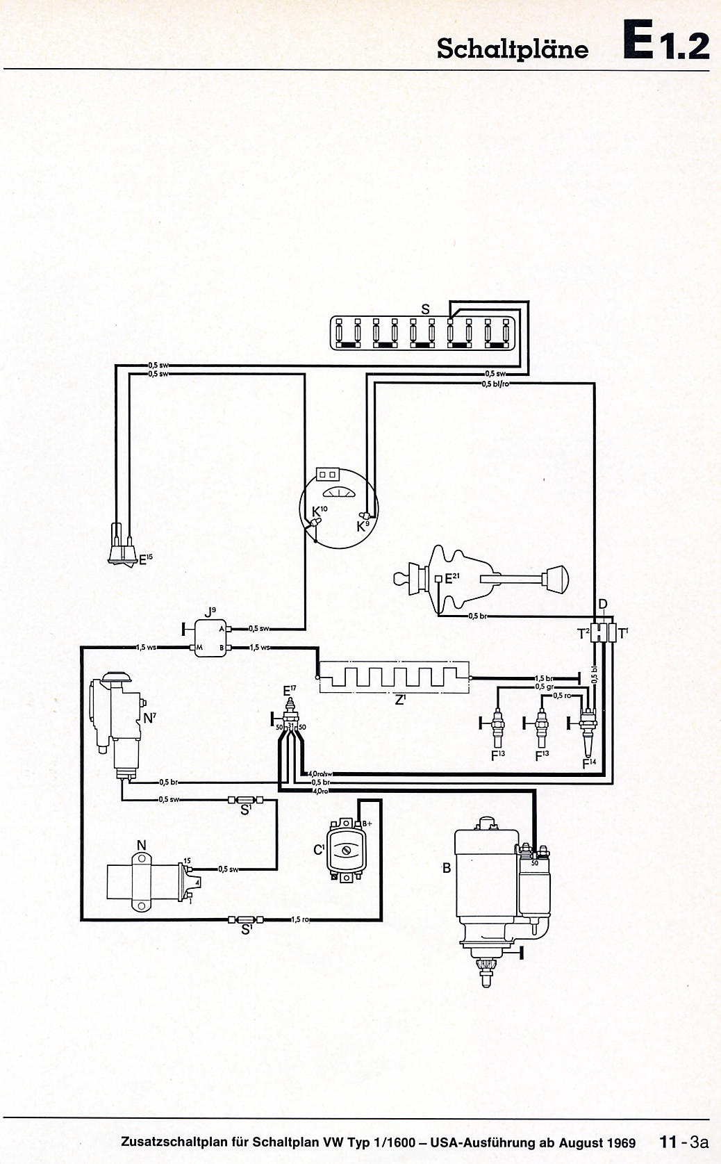
The little black toggle or rocker switch under the dash to the LH side of the steering column IS for the rear window defogger - it controls the relay under the back seat (and the pilot lamp on the speedo). The only interrelationship between that system and the charging system is that the supply wire to the relay originally connected to an auxiliary B+ terminal on the generator's voltage regulator, via an inline fuseholder. With that regulator gone, the relay may be supplied from any B+ source (either joined with the three big red wires or connected directly to the positive battery clamp)...but since there's less than a snowball's chance in hell that the window grid still works, if you won't be buying a reproduction window or applying a generic aftermarket grid there's not really much point in connecting it. No part of the rear window defogger system enters the engine compartment on a Beetle. The defogger system isn't represented on the main wiring diagram; it's shown on an an addendum along with the AutoStick wiring (another "afterthought"): http://www.vintagebus.com/wiring/Type_1 ... _items.jpg
Let's review to make sure I'm understanding the situation properly.
The alternator is an externally-regulated style with a 3-prong plug on top and a 5mm post for the B+ connection.
The regulator is for an alternator (there are a few variations but generally they're interchangeable) and has a 4-wire pigtail which goes to a rectangular white connector (or did, but you whacked it off). It's mounted to the body under the back seat, aft of the B-pillar, where the generator regulator was originally and the generator regulator has been completely removed from the car.
Three heavy red wires are all joined together under the back seat - one to the alternator, one to the battery, and one to the front of the car.
More photos are in order if the above statements are untrue, or if you find them in any way confusing.
The little black toggle or rocker switch under the dash to the LH side of the steering column IS for the rear window defogger - it controls the relay under the back seat (and the pilot lamp on the speedo). The only interrelationship between that system and the charging system is that the supply wire to the relay originally connected to an auxiliary B+ terminal on the generator's voltage regulator, via an inline fuseholder. With that regulator gone, the relay may be supplied from any B+ source (either joined with the three big red wires or connected directly to the positive battery clamp)...but since there's less than a snowball's chance in hell that the window grid still works, if you won't be buying a reproduction window or applying a generic aftermarket grid there's not really much point in connecting it. No part of the rear window defogger system enters the engine compartment on a Beetle. The defogger system isn't represented on the main wiring diagram; it's shown on an an addendum along with the AutoStick wiring (another "afterthought"): http://www.vintagebus.com/wiring/Type_1 ... _items.jpg
-
foreverska
- Posts: 137
- Joined: Tue Jun 18, 2013 11:24 am
Re: Electrical charging system issue
Wiring diagrams have nothing on this car...
In those paragraphs I realized what I should be looking for. I went and glanced under the rear seat:
Brown - DISC (Just hanging out there. I'll disconnect that on the red side immediately.)
Green - Blue (PO must've though "green is going back there already...")
Red - Connected to the wire that used to be B+ on the reg
So the fact Green/Blue came disconnected must've been keeping the alt from charging... oh well Autozone already took it back and sent off for another. So looking at the '74 and up wiring diagram Green/Blue should be tied into D+ wire on the reg. That may have been where the empty splice was on the old connector I lobbed. Given the mess that is this wiring I didn't think much of it.
For your review:
Alt, extern reg, 3 prong
Regulator, was a 4 pin mounted in the engine bay. When I bought a new reg I bought a 3 prong, lobbed off both connectors and spliced them together. I was aiming to get it road worthy immediately and I could put connectors back on later. Still tucked away in the bay.